Nissan Terrano model r20 series 2004. Manual - part 236


  Index      Nissan     Nissan Terrano model r20 series 2004 - Service and Repair Manual


Search            


Content   ..  234  235  236  237   ..


Nissan Terrano model r20 series 2004. Manual - part 236


Disassembly

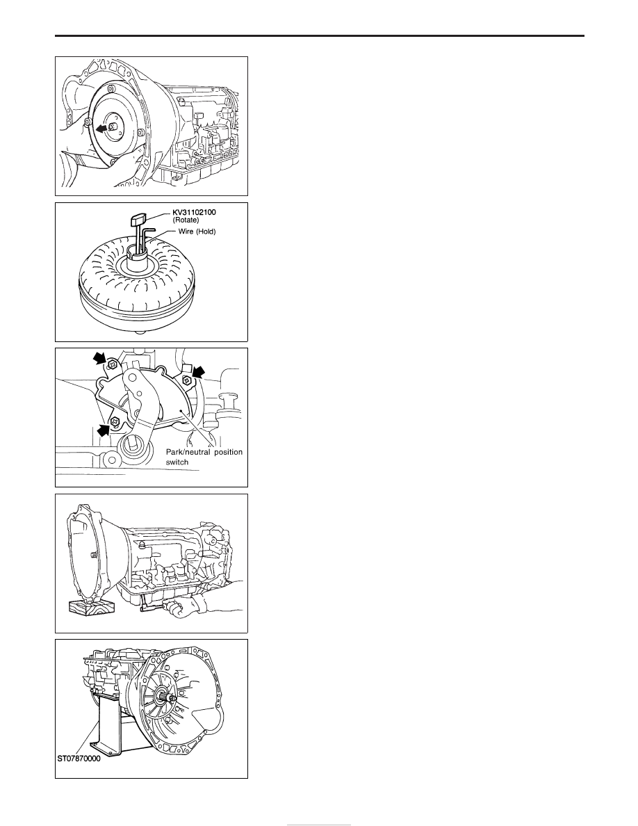
1. Drain ATF through drain plug.
2. Remove torque converter by holding it firmly and turning while

pulling straight out.

3. Check torque converter one-way clutch.
a. Insert Tool into spline of one-way clutch inner race.
b. Hook bearing support unitized with one-way clutch outer race

with suitable wire.

c. Check that one-way clutch inner race rotates only clockwise

with Tool while holding bearing support with wire.

4. Remove park/neutral position switch from transmission case.

5. Remove oil pan.

I

Always place oil pan straight down so that foreign par-
ticles inside will not move.

6. Place transmission into Tool with the control valve facing up.

SAT018B

NAT226

YAT339

SAT754I

NAT227

DISASSEMBLY

AT-128

7. Check foreign materials in oil pan to help determine cause of

malfunction. If the fluid is very dark, smells burned, or contains
foreign particles, the frictional material (clutches, band) may
need replacement. A tacky film that will not wipe clean indicates
varnish build up. Varnish can cause valves, servo, and clutches
to stick and may inhibit pump pressure.

I

If frictional material is detected, replace radiator after
repair of A/T. Refer to LC section (“Radiator”, “ENGINE
COOLING SYSTEM”).

8. Remove torque converter clutch solenoid valve and A/T fluid

temperature sensor connectors.

I

Be careful not to damage connector.

9. Remove oil strainer.
a. Remove oil strainer from control valve assembly then remove

O-ring from oil strainer.

b. Check oil strainer screen for damage.

10. Remove control valve assembly.
a. Straighten terminal clips to free terminal cords then remove

terminal clips.

SAT171B

NAT228

SAT008B

SAT025B

SAT009B

DISASSEMBLY

Disassembly (Cont’d)

AT-129

b. Remove bolts

q

A

and

q

B

, and remove control valve assembly

from transmission.

Bolt symbol

Length mm (in)

q

A

33 (1.30)

q

B

45 (1.77)

c. Remove solenoid connector.

I

Be careful not to damage connector.

d. Remove manual valve from control valve assembly.

11. Remove terminal cord assembly from transmission case while

pushing on stopper.

I

Be careful not to damage cord.

I

Do not remove terminal cord assembly unless it is dam-
aged.

SAT353B

SAT026B

SAT127B

SAT128B

DISASSEMBLY

Disassembly (Cont’d)

AT-130

12. Remove converter housing from transmission case.

I

Be careful not to scratch converter housing.

13. Remove O-ring from input shaft.

14. Remove oil pump assembly.
a. Attach Tool to oil pump assembly and extract it evenly from

transmission case.

b. Remove O-ring from oil pump assembly.
c. Remove traces of sealant from oil pump housing.

I

Be careful not to scratch pump housing.

d. Remove needle bearing and thrust washer from oil pump

assembly.

SAT999A

SAT995A

NAT229

SAT028B

SAT108B

DISASSEMBLY

Disassembly (Cont’d)

AT-131


Content   ..  234  235  236  237   ..