Nissan Terrano model r20 series 2004. Manual - part 230
8. Large Shock. “N”
→
“R” Position
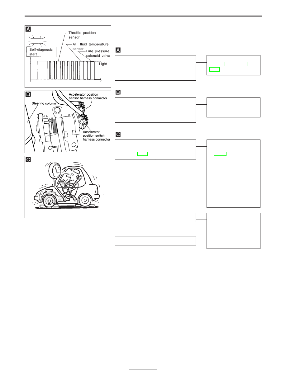
SYMPTOM:
There is large shock when changing from “N” to “R” position.
Does self-diagnosis show damage to line
pressure solenoid valve or throttle (accel-
erator) position sensor, A/T fluid tempera-
ture sensor circuit?
No
E
Yes
Check damaged circuit.
Refer to AT-62, AT-78 or
AT-86.
Check throttle (accelerator) position sen-
sor. Refer to EC section [TROUBLE
DIAGNOSIS FOR “THROTTLE (ACCEL)
POSI SEN” (DTC 43)].
OK
E
NG
Repair or replace throttle
(accelerator) position sen-
sor.
Check line pressure at idle with selector
lever in “D” position. Refer to “Line Pres-
sure Test”, AT-30.
OK
E
NG
1. Remove control valve
assembly. Refer to
AT-118.
2. Check the following
items:
I
Valves to control line
pressure (Pressure regu-
lator valve, pressure
modifier valve, pilot valve
and pilot filter)
I
Line pressure solenoid
valve
Check again.
OK
E
NG
1. Perform TCM input/
output signal inspection.
2. If NG, recheck TCM pin
terminals for damage or
loose connection with
harness connector.
INSPECTION END
SAT831HA
NAT262
SAT494G
H
H
H
H
H
DIAGNOSTIC PROCEDURES FOR SYMPTOMS
AT-104