Nissan Terrano model r20 series 2004. Manual - part 207
Control System
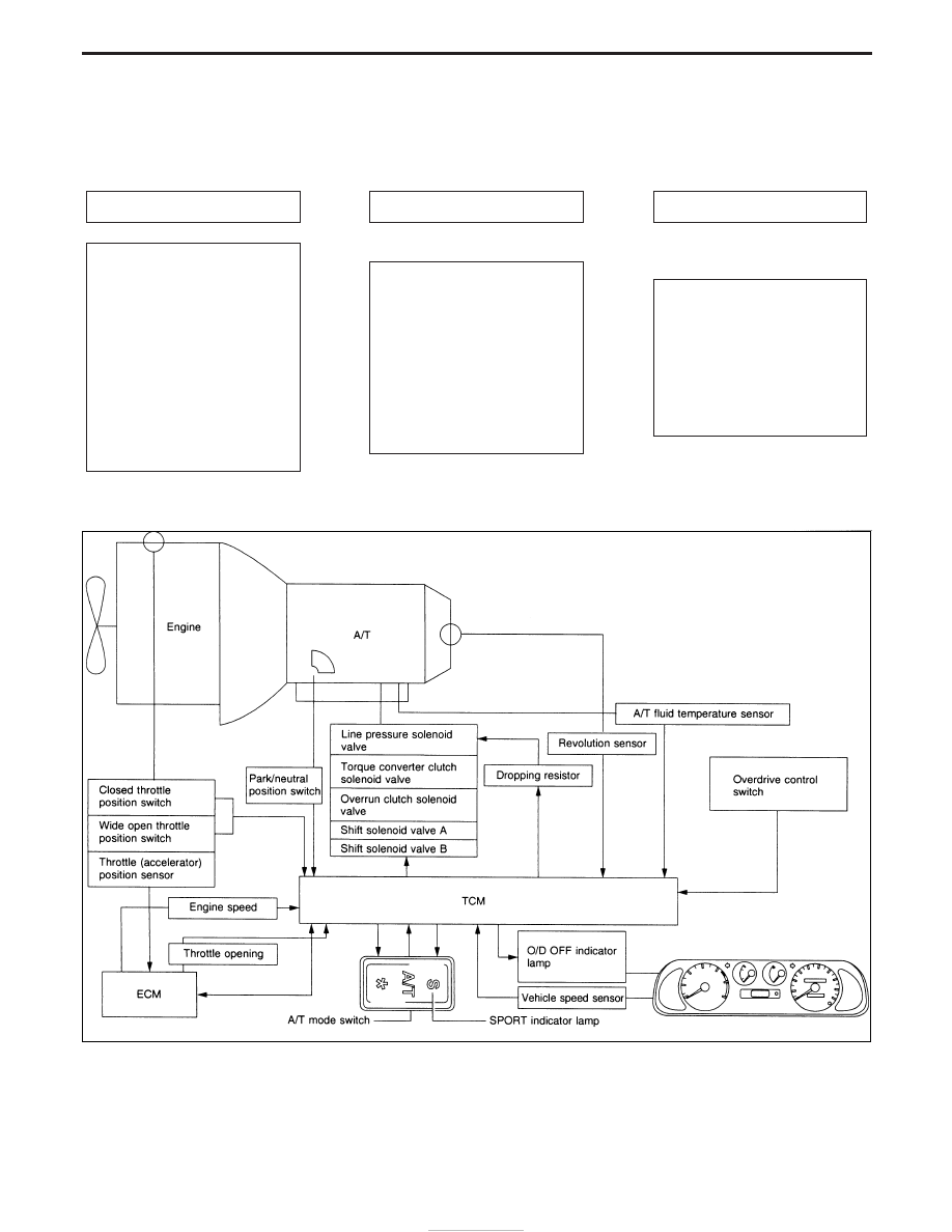
OUTLINE
The automatic transmission senses vehicle operating conditions through various sensors. It always controls
the optimum shaft position and reduces shifting and lock-up shocks.
SENSORS
TCM
ACTUATORS
Park/neutral position switch
Throttle (accelerator) position
sensor
Closed throttle position switch
Wide open throttle position
switch
Engine speed signal
A/T fluid temperature sensor
Revolution sensor
Vehicle speed sensor
Overdrive control switch
A/T mode switch
E
Shift control
Line pressure control
Lock-up control
Overrun clutch control
Timing control
Fail-safe control
Self-diagnosis
Duet-EU control
CONSULT-II communication line
control
E
Shift solenoid valve A
Shift solenoid valve B
Overrun clutch solenoid valve
Torque converter clutch
solenoid valve
Line pressure solenoid valve
O/D OFF or SPORT indicator
lamp
CONTROL SYSTEM
NAT230
OVERALL SYSTEM
AT-12