Index Nissan Nissan Terrano model r20 series 2004 - Service and Repair Manual
Search
Content .. 129 130 131 132 ..
Nissan Terrano model r20 series 2004. Manual - part 131
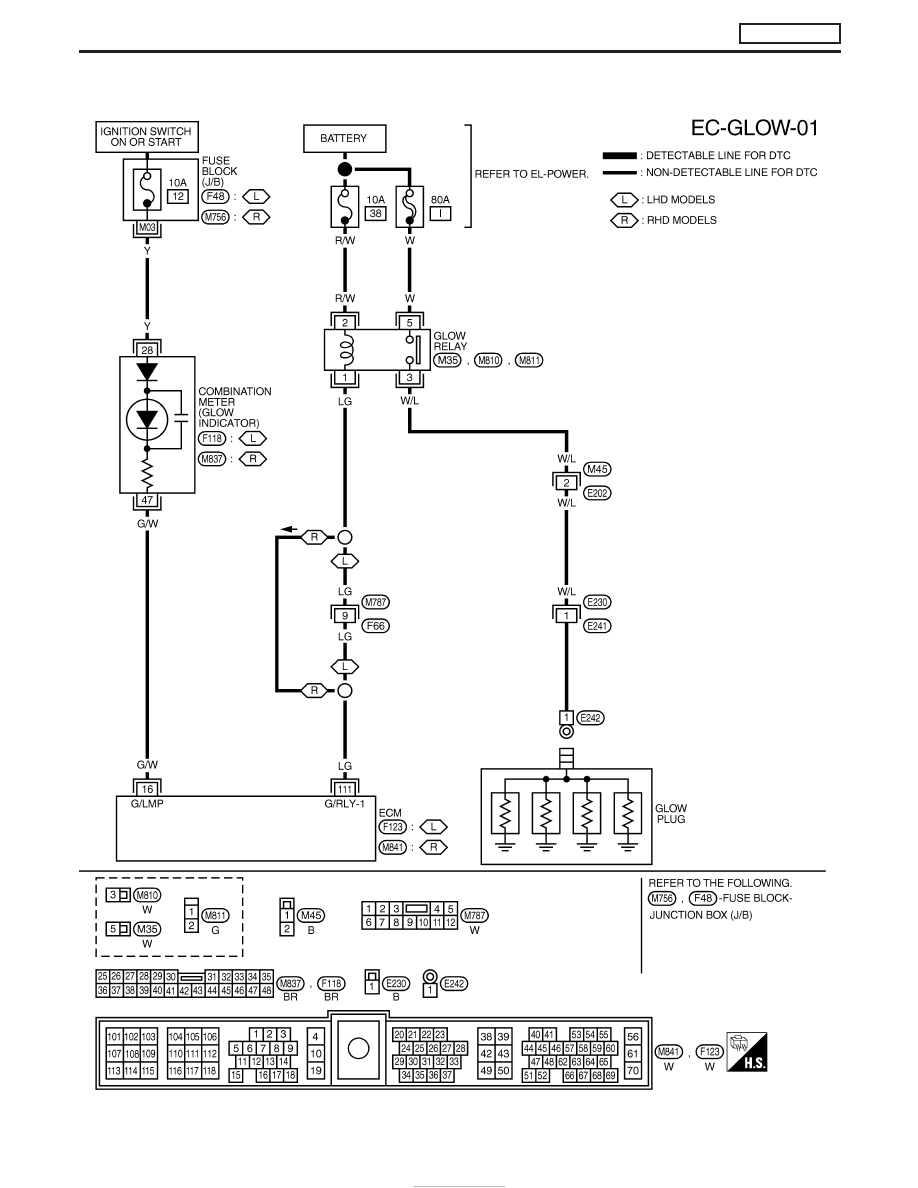
Wiring Diagram
YEC195A
GLOW CONTROL SYSTEM
ZD30DDTi
EC-246