Nissan Terrano model r20 series 2004. Manual - part 80
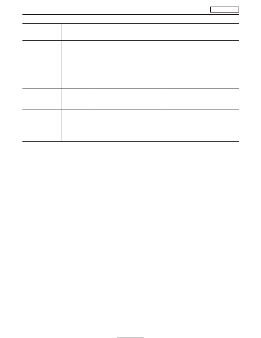
Monitored item
[Unit]
ECM
input
signals
Main
signals
Description
Remarks
EGR VOL CON/V
[step]
q
I
Indicates the EGR volume control value
computed by the ECM according to the
input signals.
I
The opening becomes larger as the
value increases.
VNT S/V 1 [%]
I
Indicates the variable nozzle turbo-
charger control solenoid valve control
value computed by the ECM according
to the input signals.
BARO SEN [kPa]
q
I
The barometric pressure (determined by
the signal voltage from the barometric
pressure sensor built into the ECM) is
displayed.
SWRL CON S/V 1
[ON/OFF]
q
I
The control condition of the swirl control
valve control solenoid valve (determined
by ECM according to the input signals) is
indicated.
I
ON ... Swirl control valve is closed.
I
OFF ... Swirl control valve is opened.
NOTE:
Any monitored item that does not match the vehicle being diagnosed is deleted from the display automatically.
ON BOARD DIAGNOSTIC SYSTEM DESCRIPTION
ZD30DDTi
CONSULT-II (Cont’d)
EC-42