Nissan Terrano r20e. Manual - part 354
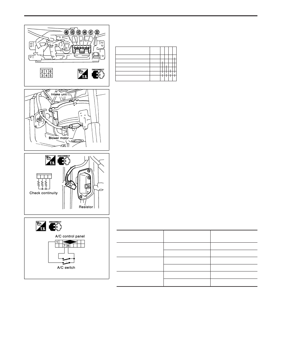
Electrical Components Inspection
FAN SWITCH
Check continuity between terminals at each switch position.
TERMINAL
LEVER
POSITION
OFF
1
2
3
4
5
o
2
o
3
o
4
o
1
o
o
o
o
6
o
o
o
o
BLOWER MOTOR
Confirm smooth rotation of the blower motor.
I
Ensure that there are no foreign particles inside the intake unit.
BLOWER RESISTOR
Check continuity between terminals.
A/C SWITCH
Check continuity between component terminals.
A/C control panel con-
nector terminal No.
A/C switch condition
Continuity
q
1
—
q
7
ON
YES
OFF
NO
q
1
—
q
8
ON
YES
OFF
NO
q
7
—
q
8
ON
YES
OFF
NO
YHA433
RHA021E
YHA434
YHA437
TROUBLE DIAGNOSES
HA-60