Nissan Terrano r20e. Manual - part 352


  Index      Nissan     Nissan Terrano r20e - Service and Repair Manual


Search            


Content   ..  350  351  352  353   ..


Nissan Terrano r20e. Manual - part 352


Diagnostic Procedure 1

SYMPTOM: Blower motor does not rotate.

I

Perform PRELIMINARY CHECK 2 before referring to the
following flow chart.

Check if blower motor rotates properly at
each fan speed.
Conduct check as per flow chart at left.

2 3 4

Eq

B

5

Eq

C

(Go to next page.)

1

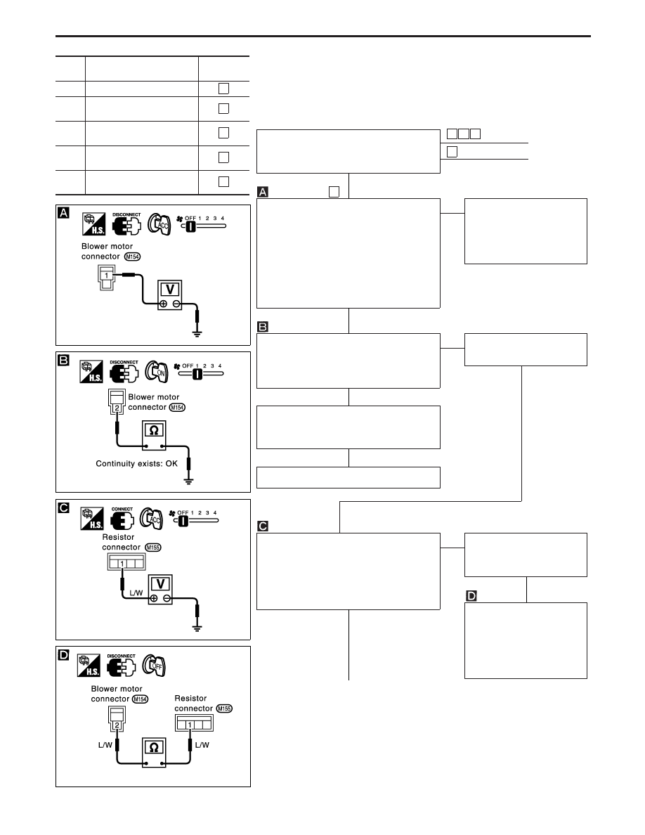
CHECK POWER SUPPLY FOR BLOWER
MOTOR.

I

Disconnect blower motor harness con-
nector.

I

Turn ignition switch to ACC or ON posi-
tion.

Do approx. 12 volts exist between blower
motor harness terminal No.

q

1

and body

ground?

OK

E

NG

Check 15A fuses at fuse
block.
(Refer to “POWER SUP-
PLY ROUTING” in EL sec-
tion and “Wiring Diagram”.)

I

Put fan switch to ON position.

Check circuit continuity between blower
motor harness terminal No.

q

2

and body

ground.

OK

E

NG

Reconnect blower motor
harness connector.

CHECK BLOWER MOTOR.
(Refer to Electrical Components Inspec-
tion.)

NG

Replace blower motor.

CHECK BLOWER MOTOR CIRCUIT
BETWEEN BLOWER MOTOR AND
RESISTOR.

I

Put fan switch to OFF position.

Do approx. 12 volts exist between resistor
harness terminal No.

q

1

and body ground?

OK

E

NG

Disconnect blower motor
and resistor harness con-
nectors.

Note

I

Turn ignition switch OFF.

Check circuit continuity
between blower motor har-
ness terminal No.

q

2

and

resistor harness terminal
No.

q

1

.

q

A

(Go to next page.)

Note:
If the result is NG after checking circuit continuity, repair har-
ness or connector.

INCIDENT

Flow chart

No.

1

Fan fails to rotate.

1

2

Fan does not rotate at
1-speed.

2

3

Fan does not rotate at
2-speed.

3

4

Fan does not rotate at
3-speed.

4

5

Fan does not rotate at
4-speed.

5

YHA408

YHA409

YHA410

YHA411

H

H

H

H

H

H

TROUBLE DIAGNOSES

HA-52

q

A

1

q

B

2

3

4

q

C

5

H

CHECK RESISTOR AFTER DISCONNECT-
ING IT.
(Refer to Electrical Components Inspection.)

OK

H

NG

Replace resistor.

Reconnect resistor harness connector.

1

2

3

4

CHECK FAN SWITCH CIRCUIT.
Do approx. 12 volts exist between each fan switch har-
ness terminal and body ground?

NG

H

OK

2

3

4

5

Note

Check circuit continuity between
fan switch and resistor.

CHECK FAN SWITCH AFTER DISCON-
NECTING IT.
(Refer to Electrical Components Inspection.)

OK

E

NG

Replace fan switch.

Note

Check circuit continuity between fan switch
harness terminal No.

q

1

and body ground.

OK

Replace blower motor.

Note:
If the result is NG after checking circuit continuity, repair har-
ness or connector.

Flow

chart

No.

Terminal No.

Voltage

!

@

q

2

Body

ground

Approx.

12V

q

3

q

4

q

5

YHA412

YHA413

YHA414

H

H

H

H

H

H

H

TROUBLE DIAGNOSES

Diagnostic Procedure 1 (Cont’d)

HA-53

Diagnostic Procedure 2

SYMPTOM: Magnet clutch does not engage when A/C

switch and fan switch are ON.

I

Perform PRELIMINARY CHECK 1 before referring to the
following flow chart.

CHECK POWER SUPPLY FOR COM-
PRESSOR.
Disconnect compressor harness connec-
tor.

I

Turn ignition switch ON and A/C switch
ON.

Do approx. 12 volts exist between com-
pressor harness terminal No.

q

1

and body

ground?

OK

E

NG

CHECK A/C RELAY
OPERATION.
Do approx. 12 volts exist
between A/C relay harness
terminal No.

q

5

and body

ground.

OK

NG

Check magnet clutch coil.

OK

q

A

q

B

Replace magnet clutch.
Refer to COMPRESSOR — Model DKV-
14C (ZEXEL make).

Note:
If the result is NG after checking circuit continuity, repair harness or connec-
tor.

YHA415

YHA416

H

H

H

H

TROUBLE DIAGNOSES

HA-54

q

A

q

B

I

Turn ignition switch OFF.

Disconnect A/C relay harness connec-
tor.

CHECK POWER SUPPLY
FOR A/C RELAY.
Disconnect A/C relay.
Do approx. 12 volts exist
between A/C relay harness
connector terminal No.

q

3

and

body ground?

NG

OK

Note

Check circuit continuity between A/C
relay harness connector terminal No.

q

5

and compressor harness connector

terminal No.

q

1

.

If NG, check harness connectors.

H

CHECK POWER SUPPLY
CIRCUIT AND 10A FUSE AT
FUSE BLOCK.
(Refer to “POWER SUPPLY
ROUTING” in EL section and
Wiring Diagram.)

I

Turn ignition switch ON.

CHECK POWER SUPPLY FOR A/C
RELAY (Coil side).
Do approx. 12 volts exist between A/C
relay harness connector terminal No.

q

2

and body ground?

H

E

NG

CHECK POWER SUPPLY
FOR A/C CONTROL PANEL.
Disconnect A/C control panel
harness connector.
Do approx. 12 volts exist
between A/C control panel
harness connector terminal
No.

q

1

and body ground?

NG

OK

F

q

C

(Go to next page.)

CHECK POWER SUPPLY
CIRCUIT AND 10A FUSE AT
FUSE BLOCK.
(Refer to “POWER SUPPLY
ROUTING” in EL section and
Wiring Diagram.)

Note:
If the result is NG after checking circuit continuity, repair harness or connec-
tor.

YHA417

YHA418

YHA419

YHA420

H

H

H

H

H

H

TROUBLE DIAGNOSES

Diagnostic Procedure 2 (Cont’d)

HA-55


Content   ..  350  351  352  353   ..