Nissan Terrano r20e. Manual - part 320
(3) Remove ball joint tightening nuts.
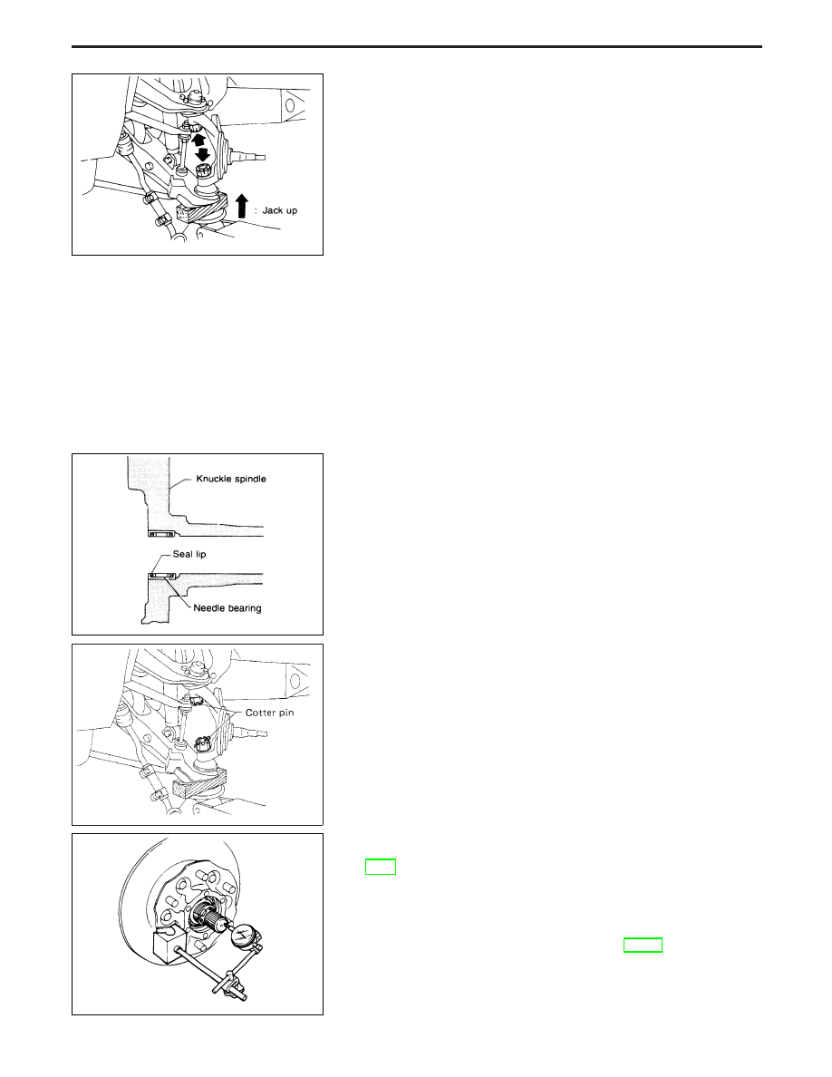
Support lower link with jack.
(4) Separate knuckle spindle from upper and lower links.
Inspection
KNUCKLE SPINDLE
I
Check knuckle spindle for deformation, cracks or other damage
by using a magnetic exploration or dyeing test.
NEEDLE BEARING
I
Check needle bearing for wear, scratches, pitting, flaking and
burn marks.
Installation
I
Install needle bearing into knuckle spindle.
Make sure that needle bearing is facing in proper direction.
Apply multi-purpose grease.
I
Install knuckle spindle to upper and lower ball joints with lower
link jacked up.
CAUTION:
Make sure that oil or grease does not come into contact with
tapered areas of ball joint and knuckle spindle and threads of
ball joint.
I
After installing knuckle spindle, adjust wheel bearing preload.
Refer to “PRELOAD ADJUSTMENT”, “Front Wheel Bearing”,
FA-6.
I
After installing drive shaft, check drive shaft axial end play.
Do not reuse snap ring once it has been removed.
Temporarily install snap ring at same thickness as it was
installed before removal.
Refer to “FRONT AXLE — Drive Shaft”, FA-22.
NFA011
NFA012
SFA929
NFA013
FRONT AXLE — Knuckle Spindle
Removal (Cont’d)
FA-21