Nissan Terrano r20e. Manual - part 305


  Index      Nissan     Nissan Terrano r20e - Service and Repair Manual


Search            


Content   ..  303  304  305  306   ..


Nissan Terrano r20e. Manual - part 305


VALVE LIFTER AND PUSH ROD
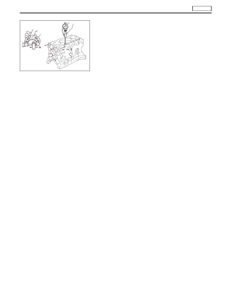
Valve lifter

1. Check valve lifters for excessive wear on the surfaces.
2. Replace with new ones if worn beyond repair.
a. Valve lifter end should be smooth.
b. Valve lifter to lifter hole clearance:

Standard

0.030 - 0.073 mm (0.0012 - 0.0029 in)

Limit

Less than 0.20 mm (0.0079 in)

Valve lifter outer diameter “A”:

Standard

25.960 - 25.970 mm (1.0220 - 1.0224 in)

Cylinder block valve lifter hole diameter “B”:

Standard

26.000 - 26.033 mm (1.0236 - 1.0249 in)

Push rod

1. Inspect push rod for excessive wear on the surfaces.
2. Replace if worn or damaged beyond repair.
3. Check push rod for bend using a dial gauge.

Maximum allowable bend
(Total indicator reading):

Less than 0.5 mm (0.020 in)

ROCKER SHAFT AND ROCKER ARM

1. Check valve rockers, brackets and rocker shafts for scoring,

wear or distortion. Replace if necessary.

SEM636B

CYLINDER HEAD

TD27Ti

Inspection (Cont’d)

EM-111

2. Check clearance between valve rockers and rocker shaft. If

specified clearance is exceeded, replace affected valve rockers
or shaft.

Specified clearance:

Limit

Less than 0.15 mm (0.0059 in)

Rocker shaft outer diameter “A”:

Standard

19.979 - 20.000 mm (0.7866 - 0.7874 in)

Rocker arm inner diameter “B”:

Standard

20.014 - 20.035 mm (0.7880 - 0.7888 in)

3. Check rocker shaft bend at its center. If bend is greater than

specified limit, replace rocker shaft.

Rocker shaft bend
(Total indicator reading):

Limit

Less than 0.3 mm (0.012 in)

MEASURING CYLINDER HEAD TO VALVE DISTANCE

Measure distance from cylinder head surface to intake and exhaust
valves. If specified distance is exceeded, replace valve(s) or valve
seat(s).

Specified distance:

Standard

Intake

0.79 - 1.19 mm
(0.0311 - 0.0469 in)

Exhaust

0.80 - 1.20 mm
(0.0315 - 0.0472 in)

Limit

Less than 1.75 mm (0.0689 in)
for intake and exhaust valves

SEM027

SEM028

SEM026

CYLINDER HEAD

TD27Ti

Inspection (Cont’d)

EM-112

Assembly

1. Assemble rocker shaft component parts.

I

Identification of rocker arms

Identification mark

(on rocker arm)

For use with

B

Intake valve

C

Exhaust valve

2. Install valve component parts.

I

Always use new valve oil seal. Refer to “VALVE STEM OIL
SEAL”.

I

Intake and exhaust valve springs are interchangeable.

3. Assemble all removed parts in reverse order of disassembly.

SEM637B

EEM093

CYLINDER HEAD

TD27Ti

EM-113

Installation

1. Install cylinder head gasket.

I

Identification of cylinder head gaskets

Identification cut hole

(on cylinder head gasket)

Inner diameter “d”

mm (in)

97 + 0.3

(3.82 + 0.012 in)

a. When replacing only cylinder head gasket, install same

grade gasket as the one formerly used.

b. When replacing or repairing cylinder block, cylinder head,

piston, connecting rod and crankshaft, select gasket as
follows:

(1) Measure piston projection.

I

Set each piston at its Top Dead Center. With piston held in that
position, measure its projections at two points.

I

Calculate the average value of the two measurements.

I

Determine the amount of projection of the other three pistons.

(2) Select suitable cylinder head gasket which conforms to the

largest amount of projection of the four pistons.

Unit: mm (in)

Average value piston

projections

Gasket thickness

Gasket grade

number

Part

no.

Less than 0.368 (0.0145)

1.20±0.05

(0.047±0.002)

2

11044

0W800

0.368 - 0.418 (0.0145 - 0.0165)

1.25±0.05

(0.049±0.002)

3

11044

0W801

More than 0.418 (0.0165)

1.30±0.05

(0.051±0.002)

4

11044

0W802

Make sure that No. 1 piston is at TDC on its compression
stroke.

NEM162

EEM104

CYLINDER HEAD

TD27Ti

EM-114


Content   ..  303  304  305  306   ..