Nissan Terrano r20e. Manual - part 281
2. Remove catalyst.
CAUTION:
Do not disassemble catalyst.
Inspection
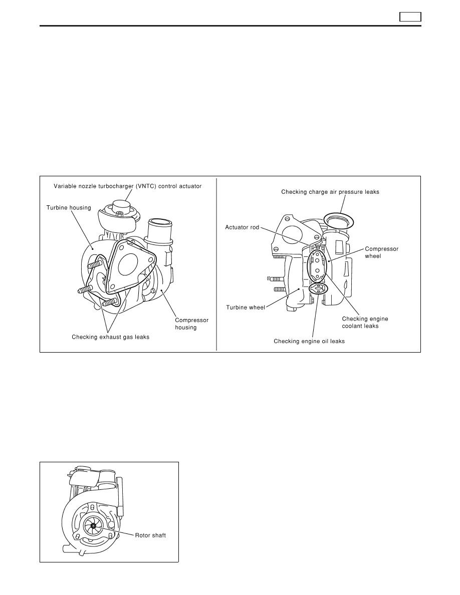
TURBOCHARGER
CAUTION:
When the compressor wheel, turbine wheel, or rotor shaft is
damaged, remove all the fragments and foreign matter left in
the following passages in order to prevent a secondary failure:
Suction side: Between turbocharger and intercooler
Exhaust side: Between turbocharger and catalytic
converter
Rotor shaft
I
Check that the rotor shaft rotates smoothly without any resis-
tance when it is rotated by your fingertips.
I
Check that the rotor shaft is not loose when it is moved verti-
cally or horizontally.
Standard value for rotor shaft oil clearance:
0.086 - 0.177 mm (0.0034 - 0.0070 in)
SEM297G
SEM298G
CATALYST AND TURBOCHARGER
ZD
Removal and Installation (Cont’d)
EM-15