Nissan Terrano r20e. Manual - part 224


  Index      Nissan     Nissan Terrano r20e - Service and Repair Manual


Search            


Content   ..  222  223  224  225   ..


Nissan Terrano r20e. Manual - part 224


Trouble Diagnoses

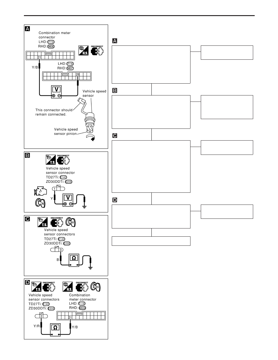
INSPECTION/VEHICLE SPEED SENSOR

CHECK VEHICLE SPEED SENSOR
OUTPUT.
1) Remove vehicle speed sensor from

transmission.

2) Check voltage between combination

meter terminals

q

21

and

q

28

while

quickly turning speed sensor pinion.

OK

E

NG

Vehicle speed sensor is
OK.

CHECK POWER SOURCE.

I

Re-install vehicle speed sensor.

I

Turn ignition switch to “ON” position.

Check voltage between vehicle speed
sensor connector terminal

q

1

and ground.

Battery voltage should exist.

OK

E

NG

Check harness for open or
short between speedom-
eter and vehicle speed
sensor.

CHECK GROUND CIRCUIT OF
VEHICLE SPEED SENSOR

I

Turn ignition switch to the “LOCK” posi-
tion.

Disconnect vehicle speed sensor connec-
tor.
Check continuity between vehicle speed
sensor harness connector terminal

q

3

and

body ground.
Continuity should exist.

OK

E

NG

Repair harness or connec-
tor

Check continuity between speedometer
harness connector terminal

q

21

and vehicle

speed sensor connector terminal

q

2

.

Continuity should exist.

OK

E

NG

Repair harness and con-
nector.

Replace vehicle speed sensor.

YEL293D

YEL294D

YEL295D

YEL296D

H

H

H

H

METER AND GAUGES

EL-79

Fuel Tank Gauge Unit Check

I

For removal, refer to FE section.

Check the resistance between terminals (G) and (E).

Ohmmeter

Float position mm (in)

Resis-

tance
value

(

)

(+)

(−)

TD27Ti

ZD30DDTi

Hardtop

models

Wagon

models

Hardtop

models

Wagon

models

G

E

*3

Full

36 (1.42) 25 (0.98) 37 (1.46) 27 (1.06)

Approx.

7

2

1/2

159

(6.26)

120

(4.72)

160

(6.30)

120

(4.72)

96 - 108

*1

Emp-

ty

286

(11.26)

218

(8.58)

282

(11.10)

220

(8.66)

280 -

290

Values *1 and *3: with the dipstick float at its lower or upper limit.

Thermal Transmitter Check

Check the resistance between the terminals of thermal transmitter
and body ground.

Water temperature

Resistance

65°C (149°F)

Approx. 951 - 1,109

91°C (196°F)

Approx. 431 - 510

Oil Pressure Switch Check

Check the continuity between the terminals of oil pressure switch
and body ground.

Oil pressure

kPa (bar, kg/cm

2

, psi)

Continuity

Engine start

More than 10 - 20 (0.10

- 0.20, 0.1 - 0.2, 1.4 -

2.8)

NO

Engine stop

Less than 10 - 20 (0.10 -

0.20, 0.1 - 0.2, 1.4 - 2.8)

YES

YEL297D

SEL233P

SEL748K

METER AND GAUGES

EL-80

Schematic

YEL098D

WARNING LAMPS AND CHIME

EL-81

Wiring Diagram — WARN —

LHD MODELS

YEL099D

WARNING LAMPS AND CHIME

EL-82


Content   ..  222  223  224  225   ..