Index Nissan Nissan Terrano r20e - Service and Repair Manual
Search
Content .. 221 222 223 224 ..
Nissan Terrano r20e. Manual - part 223
ZD30DDTi ENGINE MODELS
YEL097D
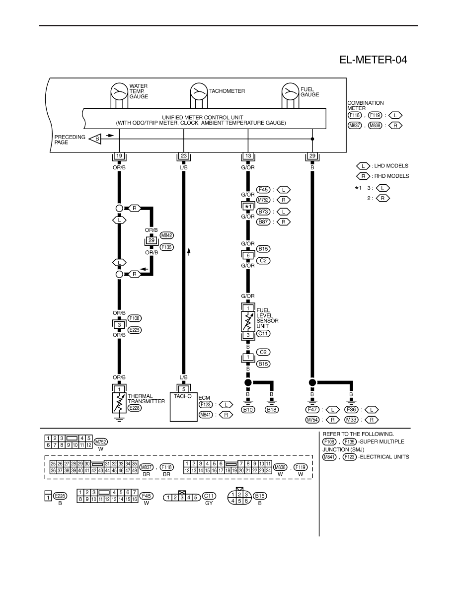
METER AND GAUGES
Wiring Diagram — METER — (Cont’d)
EL-75