Nissan Terrano r20e. Manual - part 115


  Index      Nissan     Nissan Terrano r20e - Service and Repair Manual


Search            


Content   ..  113  114  115  116   ..


Nissan Terrano r20e. Manual - part 115


Diagnostic Procedure

1

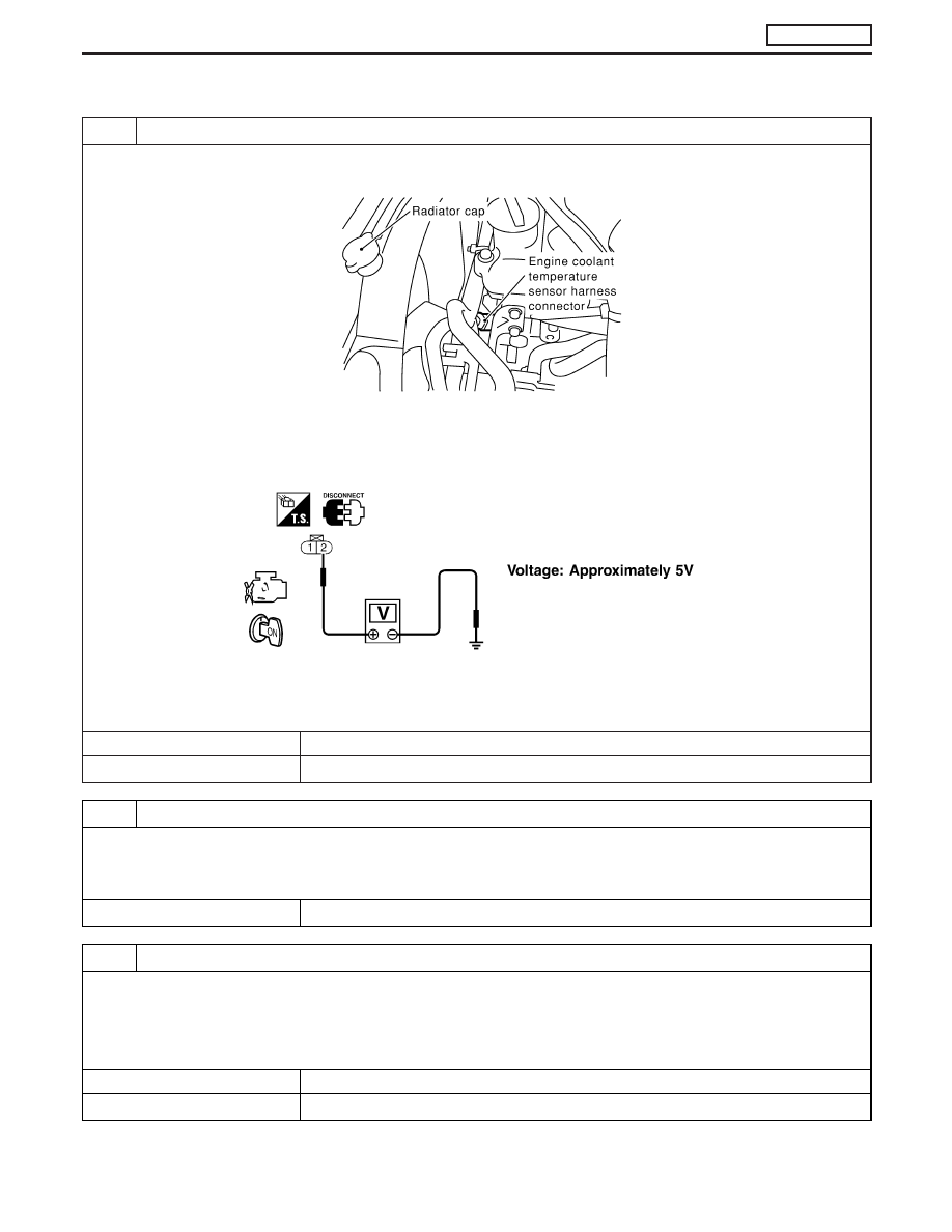
CHECK ECTS POWER SUPPLY CIRCUIT

1. Turn ignition switch “OFF”.
2. Disconnect engine coolant temperature sensor harness connector.

MEC022E

3. Turn ignition switch “ON”.
4. Check voltage between ECTS terminal 2 and ground with CONSULT-II or tester.

SEF401Y

OK or NG

OK

E

GO TO 3.

NG

E

GO TO 2.

2

DETECT MALFUNCTIONING PART

Check the following.

I

Harness connectors E225, F108

I

Harness connectors F135, M842 (RHD models)

I

Harness for open or short between engine control temperature sensor and ECM

E

Repair open circuit or short to ground or short to power in harness or connectors.

3

CHECK ECTS GROUND CIRCUIT FOR OPEN AND SHORT

1. Turn ignition switch “OFF”.
2. Check harness continuity between ECTS terminal 1 and engine ground. Refer to Wiring Diagram.

Continuity should exist.

3. Also check harness for short to ground and short to power.

OK or NG

OK

E

GO TO 5.

NG

E

GO TO 4.

DTC 0103 COOLANT TEMP SEN

ZD30DDTi

EC-97

4

DETECT MALFUNCTIONING PART

Check the following.

I

Harness connectors E225, F108

I

Harness connectors F135, M842 (RHD models)

I

Harness for open or short between engine coolant temperature sensor and ECM

E

Repair open circuit or short to ground or short to power in harness or connectors.

5

CHECK ENGINE COOLANT TEMPERATURE SENSOR

1. Remove engine coolant temperature sensor from the engine.
2. Check resistance between ECTS terminals 1 and 2 as shown in the figure.

SEF304X

OK or NG

OK

E

GO TO 6.

NG

E

Replace engine coolant temperature sensor.

6

CHECK INTERMITTENT INCIDENT

Refer to “TROUBLE DIAGNOSIS FOR INTERMITTENT INCIDENT”, EC-78.

E

INSPECTION END

DTC 0103 COOLANT TEMP SEN

ZD30DDTi

Diagnostic Procedure (Cont’d)

EC-98

Description

The vehicle speed sensor is installed in the transaxle. It contains a
pulse generator which provides a vehicle speed signal to the
speedometer. The speedometer then sends a signal to the ECM.

ECM Terminals and Reference Value

Specification data are reference values and are measured between each terminal and ground.

CAUTION:

Do not use ECM ground terminals when measuring input/output voltage. Doing so may damage the
ECM’s transistor. Use a ground other than ECM terminals, such as the ground.

TER-

MINAL

NO.

WIRE

COLOR

ITEM

CONDITION

DATA (DC Voltage and

Pulse Signal)

26

Y/B

Vehicle speed sensor

Engine is running.

Lift up the vehicle
In 1st gear position
Vehicle speed is 10 km/h (6 MPH)

0 - Approximately 4.8V

SEF257Z

Engine is running.

Lift up the vehicle
In 2nd gear position
Vehicle speed is 30 km/h (19 MPH)

Approximately 2.2V

SEF258Z

On Board Diagnosis Logic

Malfunction is detected when ....

Check Items (Possible Cause)

I

The almost 0 km/h (0 MPH) signal from vehicle speed sensor
is sent to ECM even when vehicle is being driven.

I

Harness or connector
(The vehicle speed sensor circuit is open or shorted.)

I

Vehicle speed sensor

AEC110

DTC 0104 VEHICLE SPEED SEN

ZD30DDTi

EC-99

Overall Function Check

Use this procedure to check the overall function of the vehicle
speed sensor circuit. During this check, a DTC might not be con-
firmed.

WITH CONSULT-II

1) Lift up the vehicle.
2) Start engine.
3) Read vehicle speed sensor signal in “DATA MONITOR” mode

with CONSULT-II.
The vehicle speed on CONSULT-II should be able to exceed
10 km/h (6 MPH) when rotating wheels with suitable gear
position.

4) If NG, go to “Diagnostic Procedure”, EC-103.

WITHOUT CONSULT-II

1) Lift up the vehicle.
2) Start engine.
3) Rotate drive wheel by hand.
4) Check voltage between ECM terminal 26 and ground with

tester.
Voltage should vary between 0 - BATTERY VOLTAGE.

5) If NG, go to “Diagnostic Procedure”, EC-103.

SEF864Y

SEF811R

DTC 0104 VEHICLE SPEED SEN

ZD30DDTi

EC-100


Content   ..  113  114  115  116   ..