Nissan Terrano r20e. Manual - part 100


  Index      Nissan     Nissan Terrano r20e - Service and Repair Manual


Search            


Content   ..  98  99  100  101   ..


Nissan Terrano r20e. Manual - part 100


Diagnostic test mode I — Bulb check

In this mode, the MI on the instrument panel should stay ON. If it remains OFF, check the bulb. Refer to EL
section, “WARNING LAMPS AND CHIME” or see EC-291.

Diagnostic test mode I — Malfunction warning

MI

Condition

ON

When the malfunction is detected or the ECM’s CPU is malfunctioning.

OFF

No malfunction.

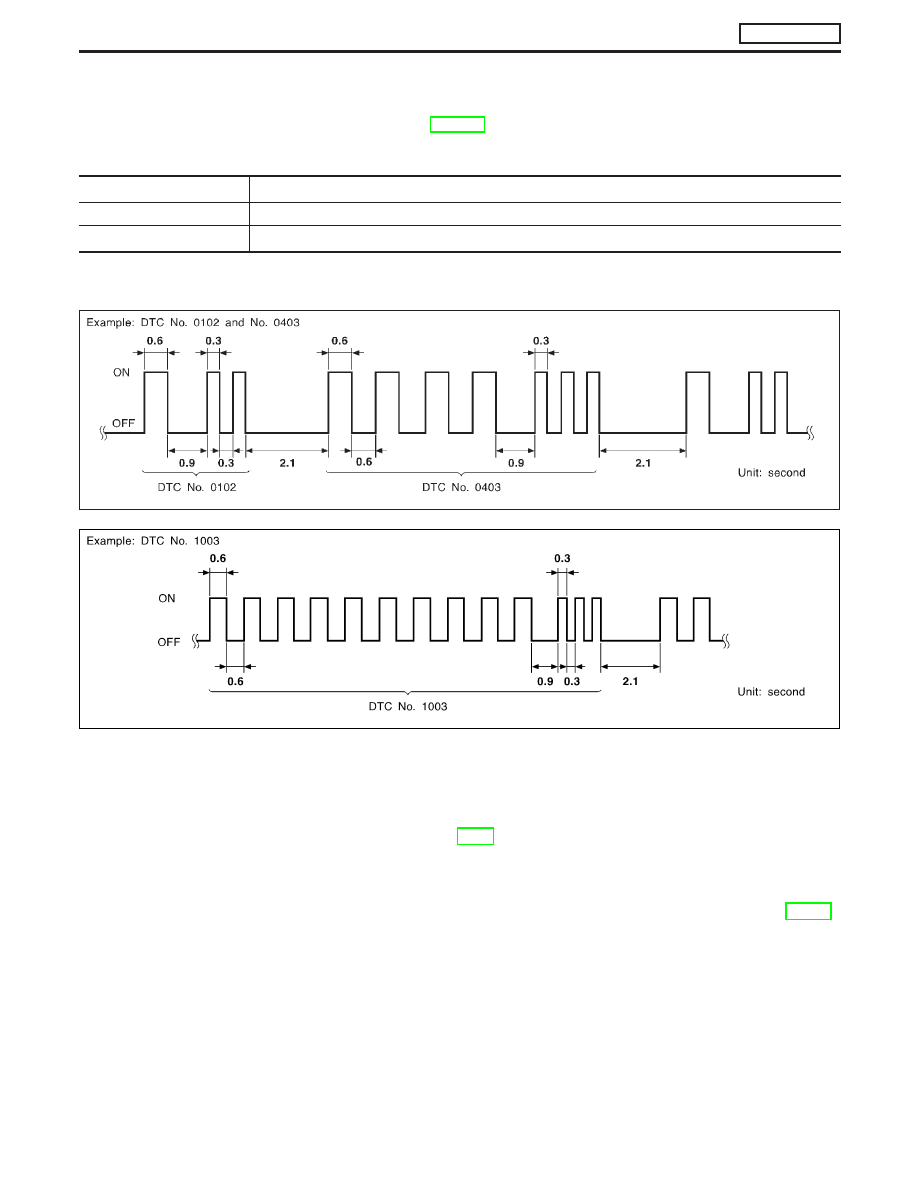
Diagnostic test mode II — Self-diagnostic results

In this mode, DTC is indicated by the number of blinks of the MI as shown below.

Long (0.6 second) blinking indicates the two LH digits of number and short (0.3 second) blinking indicates the
two RH digits of number. For example, the MI blinks 10 times for 6 seconds (0.6 sec x 10 times) and then it
blinks three times for about 1 second (0.3 sec x 3 times). This indicates the DTC “1003”.
In this way, all the detected malfunctions are classified by their DTC numbers. The DTC “0505” refers to no
malfunction. (See TROUBLE DIAGNOSIS — INDEX, EC-7.)

How to erase diagnostic test mode II (Self-diagnostic results)

The DTC can be erased from the backup memory in the ECM when the diagnostic test mode is changed from
Diagnostic Test Mode II to Diagnostic Test Mode I. (Refer to “How to Switch Diagnostic Test Modes”, EC-36.)

I

If the battery terminal is disconnected, the DTC will be lost from the backup memory within 24
hours.

I

Be careful not to erase the stored memory before starting trouble diagnoses.

SEF298QA

SEF162PB

ON BOARD DIAGNOSTIC SYSTEM DESCRIPTION

ZD30DDTi

Malfunction Indicator (MI) (Cont’d)

EC-37

Relationship between MI, DTC, CONSULT-II and driving patterns

*1: When a malfunction is detected,

MI will light up.

*2: MI will not light up after ignition

switch is turned OFF.

*3: When a malfunction is detected

for the first time, the DTC will be
stored in ECM.

*4: The DTC will not be displayed any

longer after vehicle is driven 40
times without the same malfunc-
tion. (The DTC still remain in
ECM.)

*5: Other screens except SELF-DIAG-

NOSTIC RESULTS & DATA
MONITOR (AUTO TRIG) cannot
display the malfunction. DATA
MONITOR (AUTO TRIG) can dis-
play the malfunction at the
moment it is detected.

PBIB0589E

ON BOARD DIAGNOSTIC SYSTEM DESCRIPTION

ZD30DDTi

Malfunction Indicator (MI) (Cont’d)

EC-38

CONSULT-II

CONSULT-II INSPECTION PROCEDURE

1. Turn ignition switch OFF.
2. Connect CONSULT-II to data link connector, which is located

under the driver side dash panel.

3. Turn ignition switch ON.
4. Touch “START”.
5. Touch “ENGINE”.
6. Perform each diagnostic test mode according to each service

procedure.

For further information, see the CONSULT-II Operation Manual.

MEC992D

SEF995X

SEF320Y

ON BOARD DIAGNOSTIC SYSTEM DESCRIPTION

ZD30DDTi

EC-39

ENGINE CONTROL COMPONENT PARTS/CONTROL
SYSTEMS APPLICATION

Item

DIAGNOSTIC TEST MODE

SELF-DIAG

RESULTS

DATA MONI-

TOR

ACTIVE

TEST

ENGINE

CONTROL

COMPONENT

P

ARTS

INPUT

Engine coolant temperature sensor

X

X

Vehicle speed sensor

X

X

Accelerator position sensor

X

X

X

Accelerator position switch

X

X

Accelerator switch (F/C)

X

X

Crankshaft position sensor (TDC)

X

X

Ignition switch (start signal)

X

Park/Neutral position (PNP) switch

X

Battery voltage

X

Air conditioner switch

X

Mass air flow sensor

X

X

Stop lamp switch

X

X

Heat up switch

X

Charge air pressure sensor

X

OUTPUT

Glow relay

X

X

EGR volume control valve

X

X

X

Cooling fan relay

X

X

X

Air conditioner relay

X

Variable nozzle turbocharger control solenoid valve

X

Swirl control valve control solenoid valve

X

X

X: Applicable

SELF-DIAGNOSTIC MODE

Regarding items detected in “SELF-DIAG RESULTS” mode,
refer to “TROUBLE DIAGNOSIS — INDEX”, EC-7.

DATA MONITOR MODE

Monitored item
[Unit]

ECM
input

signals

Main

signals

Description

Remarks

CKPS

RPM (TDC)

[rpm]

q

q

I

The engine speed computed from the
crankshaft position sensor (TDC) signal
is displayed.

CMPS

RPM

PUMP

[rpm]

q

q

I

The engine speed computed from the
pulse signal sent from electronic control
fuel injection pump is displayed.

COOLAN TEMP/S
[°C] or [°F]

q

q

I

The engine coolant temperature (deter-
mined by the signal voltage of the engine
coolant temperature sensor) is displayed.

I

When the engine coolant temperature
sensor is open or short-circuited, ECM
enters fail-safe mode. The engine cool-
ant temperature determined by the ECM
is displayed.

VHCL SPEED SE
[km/h] or [mph]

q

q

I

The vehicle speed computed from the
vehicle speed sensor signal is displayed.

ON BOARD DIAGNOSTIC SYSTEM DESCRIPTION

ZD30DDTi

CONSULT-II (Cont’d)

EC-40


Content   ..  98  99  100  101   ..