Nissan Terrano r20e. Manual - part 96


  Index      Nissan     Nissan Terrano r20e - Service and Repair Manual


Search            


Content   ..  94  95  96  97   ..


Nissan Terrano r20e. Manual - part 96


Normal control

Input/output signal chart

Sensor

Input Signal to ECM

ECM Function

Actuator

Crankshaft position sensor (TDC)

Engine speed

Fuel injection con-
trol (Normal con-
trol)

Electronic control fuel injec-
tion pump

Accelerator position sensor

Accelerator position

Vehicle speed sensor

Vehicle speed

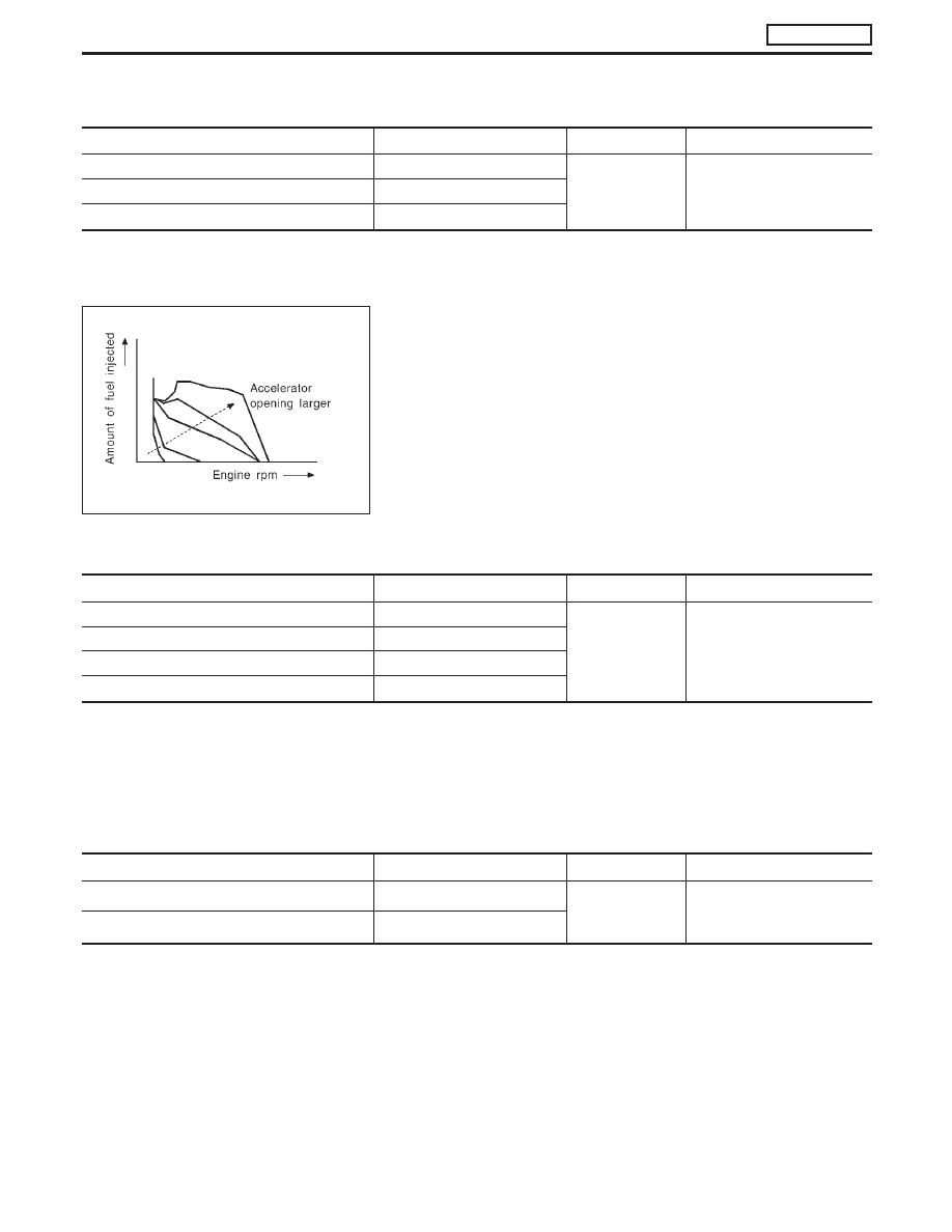
The amount of fuel injected under normal driving conditions is
determined according to sensor signals. The crankshaft position
sensor (TDC) detects engine speed and the accelerator position
sensor detects accelerator position. These sensors send signals to
the ECM.
The fuel injection data, predetermined by correlation between vari-
ous engine speeds and accelerator positions, are stored in the
ECM memory, forming a map. The ECM determines the optimal
amount of fuel to be injected using the sensor signals in compari-
son with the map.

Maximum amount control

Input/output signal chart

Sensor

Input Signal to ECM

ECM Function

Actuator

Mass air flow sensor

Amount of intake air

Fuel injection con-
trol (Maximum
amount control)

Electronic control fuel injec-
tion pump

Engine coolant temperature sensor

Engine coolant temperature

Crankshaft position sensor (TDC)

Engine speed

Accelerator position sensor

Accelerator position

The maximum injection amount is controlled to an optimum by the engine speed, intake air amount, engine
coolant temperature, and accelerator opening in accordance with the driving conditions.
This prevents the oversupply of the injection amount caused by decreased air density at a high altitude or
during a system failure.

Deceleration control

Input/output signal chart

Sensor

Input Signal to ECM

ECM Function

Actuator

Accelerator switch (F/C)

Accelerator position

Fuel injection con-
trol (Deceleration
control)

Electronic control fuel injec-
tion pump

Crankshaft position sensor (TDC)

Engine speed

The ECM sends a fuel cut signal to the electronic control fuel injection pump during deceleration for better
fuel efficiency. The ECM determines the time of deceleration according to signals from the accelerator switch
(F/C) and crankshaft position sensor (TDC).

SEF649S

ENGINE AND EMISSION BASIC CONTROL SYSTEM

DESCRIPTION

ZD30DDTi

Fuel Injection Control System (Cont’d)

EC-21

Fuel Injection Timing Control System

DESCRIPTION

The target fuel injection timing in accordance with the engine speed and the fuel injection amount are recorded
as a map in the ECM beforehand. The ECM and the injection pump control unit exchange signals and per-
form feedback control for optimum injection timing in accordance with the map.

Air Conditioning Cut Control

DESCRIPTION

Input/output signal chart

Sensor

Input Signal to ECM

ECM Function

Actuator

Air conditioner switch

Air conditioner “ON” signal

Air conditioner cut
control

Air conditioner relay

Accelerator position sensor

Accelerator valve opening
angle

Vehicle speed sensor

Vehicle speed

Engine coolant temperature sensor

Engine coolant temperature

System description

This system improves acceleration when the air conditioner is used.
When the accelerator pedal is fully depressed, the air conditioner is turned off for a few seconds.
When engine coolant temperature becomes excessively high, the air conditioner is turned off. This continues
until the engine coolant temperature returns to normal.

Fuel Cut Control (at no load & high engine
speed)

DESCRIPTION

Input/output signal chart

Sensor

Input Signal to ECM

ECM Function

Actuator

Vehicle speed sensor

Vehicle speed

Fuel cut control

Electronic control fuel injec-
tion pump

Park/Neutral position (PNP) switch

Neutral position

Accelerator position switch or Accelerator
switch (F/C)

Accelerator position

Engine coolant temperature sensor

Engine coolant temperature

Crankshaft position sensor (TDC)

Engine speed

If the engine speed is above 2,700 rpm with no load (for example, in neutral and engine speed over 2,700
rpm) fuel will be cut off after some time. The exact time when the fuel is cut off varies based on engine speed.
Fuel cut will operate until the engine speed reaches 1,500 rpm, then fuel cut is cancelled.
NOTE:
This function is different from deceleration control listed under “Fuel Injection Control System”, EC-20.

ENGINE AND EMISSION BASIC CONTROL SYSTEM

DESCRIPTION

ZD30DDTi

EC-22

Crankcase Ventilation System

DESCRIPTION

In this system, blow-by gas is sucked into the air inlet pipe after oil
separation by oil separator in the rocker cover.

INSPECTION

Ventilation hose

1. Check hoses and hose connections for leaks.
2. Disconnect all hoses and clean with compressed air. If any

hose cannot be freed of obstructions, replace.

JEF224Z

SEC692

ENGINE AND EMISSION BASIC CONTROL SYSTEM

DESCRIPTION

ZD30DDTi

EC-23

Injection Tube and Injection Nozzle

REMOVAL AND INSTALLATION

CAUTION:

I

Do not disassemble injection nozzle assembly. If NG,
replace injection nozzle assembly.

I

Plug flare nut with a cap or rag so that no dust enters the
nozzle. Cover nozzle tip for protection of needle.

Injection tube

Removal
1. Mark the cylinder Nos. to the injection tubes, then disconnect

them.

I

Marking should be made at proper locations and by the
proper method, so that they are not erased by fuel, etc.

2. Remove the clamps, then disconnect the tubes one by one.

I

Avoid letting leaked fuel get on the interior walls of the
engine compartment.

Take special care to prevent fuel from getting on the engine
mount insulator.

JEF237Z

JEF238Z

BASIC SERVICE PROCEDURE

ZD30DDTi

EC-24


Content   ..  94  95  96  97   ..