Nissan Terrano r20e. Manual - part 70


  Index      Nissan     Nissan Terrano r20e - Service and Repair Manual


Search            


Content   ..  68  69  70  71   ..


Nissan Terrano r20e. Manual - part 70


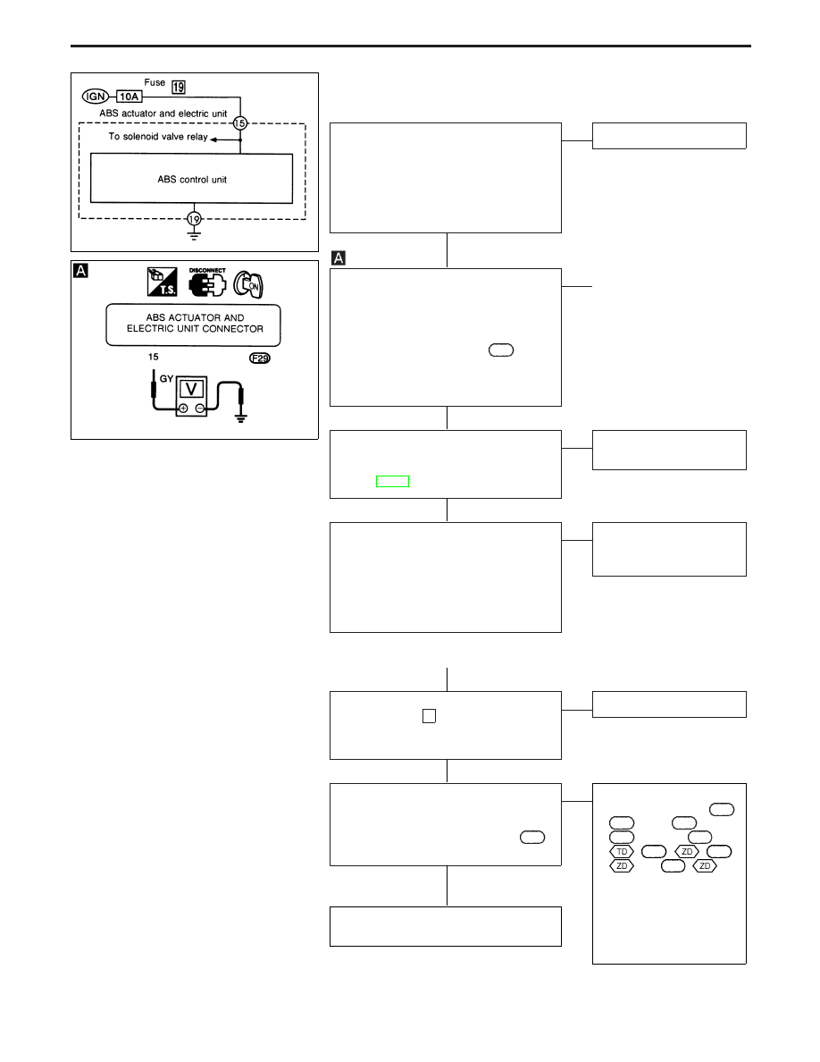
Diagnostic Procedure 7 (Low voltage)

Malfunction code No. 57

CHECK CONNECTOR.
1. Disconnect ABS actuator and electric

unit connector. Check terminals for
damage or loose connections. Then
reconnect connector.

2. Carry out self-diagnosis again.

Does warning lamp activate again?

Yes

E

No

Inspection end

CHECK ABS CONTROL UNIT POWER
SUPPLY CIRCUIT
1. Disconnect ABS actuator and electric

unit connector.

2. Check voltage between ABS actuator

and electric unit connector

F29

termi-

nal

q

15

and ground.

Battery voltage should exist when
ignition switch is turned ON.

OK

E

NG

q

A

(See below.)

CHECK ABS CONTROL UNIT GROUND
Refer to ABS ACTUATOR AND ELEC-
TRIC UNIT GROUND in Ground Circuit
Check, BR-66.

OK

E

NG

Repair harness and con-
nector.

CHECK HARNESS CONNECTOR.
Check ABS actuator and electric unit pin
terminals for damage or the connection of
ABS actuator and electric unit harness
connector. Reconnect ABS actuator and
electric unit harness connector. Then
retest.

E

NG

Replace
Replace ABS actuator and
electric unit

q

A

CHECK FUSE.
Check 10A fuse

19

. For fuse layout, refer

to POWER SUPPLY ROUTING in EL sec-
tion.

OK

E

NG

Replace fuse.

CHECK ABS CONTROL UNIT POWER
SUPPLY CIRCUIT
Check continuity between fuse and ABS
actuator and electric unit connector

F29

(body side) terminal

q

15

.

OK

E

NG

Check the following:

I

Harness connector

F29

,

M822

, LHD:

F66

and

M787

, or RHD:

F76

:

,

F136

:

,

M743

:

and

M829

:

I

Harness for open or
short between ABS
actuator and electric unit
and fuse

If NG, repair harness or
connector.

Check battery. Refer to BATTERY in EL
section.

NBR337

NBR338

H

H

H

H

H

H

TROUBLE DIAGNOSES

BR-77

Diagnostic Procedure 8 (G sensor)

Malfunction code No. 17

CHECK G SENSOR POWER SUPPLY
CIRCUIT.
Check 10A fuse

19

. For fuse layout,

refer to POWER SUPPLY ROUTING in
EL section.

OK

E

NG

Replace fuse.

CHECK CONNECTOR.
1. Disconnect ABS actuator and electric

unit connector. Check terminals for
damage or loose connection. Then
reconnect connector.

2. Carry out self-diagnosis again.

Does warning lamp activate again?

Yes

E

No

Inspection end

CHECK G SENSOR.
Refer to G SENSOR in Electrical Compo-
nents Inspection, BR-83

OK

E

NG

Replace G sensor.

CHECK G SENSOR POWER SUPPLY
CIRCUIT.
1. Disconnect G sensor connectors.
2. Check voltage between G sensor con-

nector terminals

q

1

(

B59

),

q

3

(

B60

)

and ground.
Battery voltage should exist.

OK

E

NG

Check the following.

I

Harness connectors

B59

,

B60

, LHD:

B73

,

RHD:

B67

, LHD:

F66

,

RHD:

F76

:

, RHD:

F136

:

, LHD:

M787

,

RHD:

M743

:

, RHD:

M829

:

, LHD:

F45

,

RHD:

F80

and

M822

I

Harness for open or
short between G sensor
and ABS actuator and
electric unit

If NG, repair harness or
connectors.

CHECK G SENSOR GROUND.
1. Disconnect ABS actuator and electric

unit connector and G sensor connec-
tors.

2. Check continuity between ABS actuator

and electric unit connector

F29

(body

side) terminals

q

20

,

q

10

and G sensor

connectors (body side) terminals

q

2

(

B59

),

q

4

(

B60

).

Continuity should exist.

OK

E

NG

Check the following.

I

Harness connectors

B59

,

B60

, LHD:

B73

,

RHD:

B67

,

F29

, LHD:

F45

and RHD:

F80

I

Harness for open or
short between G sensor
and ABS actuator and
electric unit

If NG, repair harness or
connectors.

CHECK HARNESS CONNECTOR.
Check ABS actuator and electric unit pin
terminals for damage or the connection of
ABS actuator and electric unit harness
connector. Reconnect ABS actuator and
electric unit harness connector. Then
retest.

YBR276

YBR277

YBR278

H

H

H

H

H

TROUBLE DIAGNOSES

BR-78

Diagnostic Procedure 9 (Control unit)

Malfunctioning code No. 71

CHECK CONNECTOR.
1. Disconnect ABS actuator and electric

unit connector.
Check terminals for damage or loose
connections. Then reconnect connector.

2. Carry out self-diagnosis again.

Does warning lamp activate again?

Yes

E

No

Inspection end

CHECK ABS ACTUATOR AND ELEC-
TRIC UNIT POWER SUPPLY CIRCUIT
Check voltage. Refer to

in Diagnostic

Procedure 7, BR-77.

CHECK SELF-DIAGNOSTIC RESULTS
Does warning lamp indicate code No. 71
again?

No

E

Yes

Replace ABS actuator and
electric unit.

INSPECTION
Inspect the system according to the code
No.

NBR343

H

H

H

TROUBLE DIAGNOSES

BR-79

Diagnostic Procedure 10 (Pedal vibration and
noise)

INSPECTION START
1. Apply brake.
2. Start engine.
3. Does the symptom appear only when

engine is started?

No

E

Yes

Carry out self-diagnosis.
Refer to BR-59.

CHECK IF SYMPTOM APPEARS.
Does the symptom appear when electrical
equipment switches (such as headlamp)
are operated?

Yes

E

No

Go to

in Diagnostic

Procedure 12, BR-81.

CHECK WHEEL SENSOR.
Check wheel sensor shield ground. For
location of shield ground, refer to wiring
diagram and “HARNESS LAYOUT” in EL
section.

OK

E

NG

Repair wheel sensor.

CHECK HARNESS CONNECTOR.
Check ABS actuator and electric unit pin
terminals for damage or the connection of
ABS actuator and electric unit harness
connector.
Reconnect ABS actuator and electric unit
harness connector. Then retest.

Note: ABS may operate and cause vibration under any of the

following conditions.

Diagnostic Procedure 11 (Long stopping
distance)

CHECK ABS PERFORMANCE
Disconnect ABS actuator and electric unit
connector and check whether stopping
distance is still long.

Yes

E

No

Go to

in Diagnostic

Procedure 12, BR-81.

Perform Preliminary Check and air bleed-
ing.

Note: Stopping distance may be larger than vehicles without

ABS when road condition is slippery.

SAT797A

H

H

H

H

TROUBLE DIAGNOSES

BR-80


Content   ..  68  69  70  71   ..