Nissan Terrano r20e. Manual - part 65


  Index      Nissan     Nissan Terrano r20e - Service and Repair Manual


Search            


Content   ..  63  64  65  66   ..


Nissan Terrano r20e. Manual - part 65


YBR252

TROUBLE DIAGNOSES

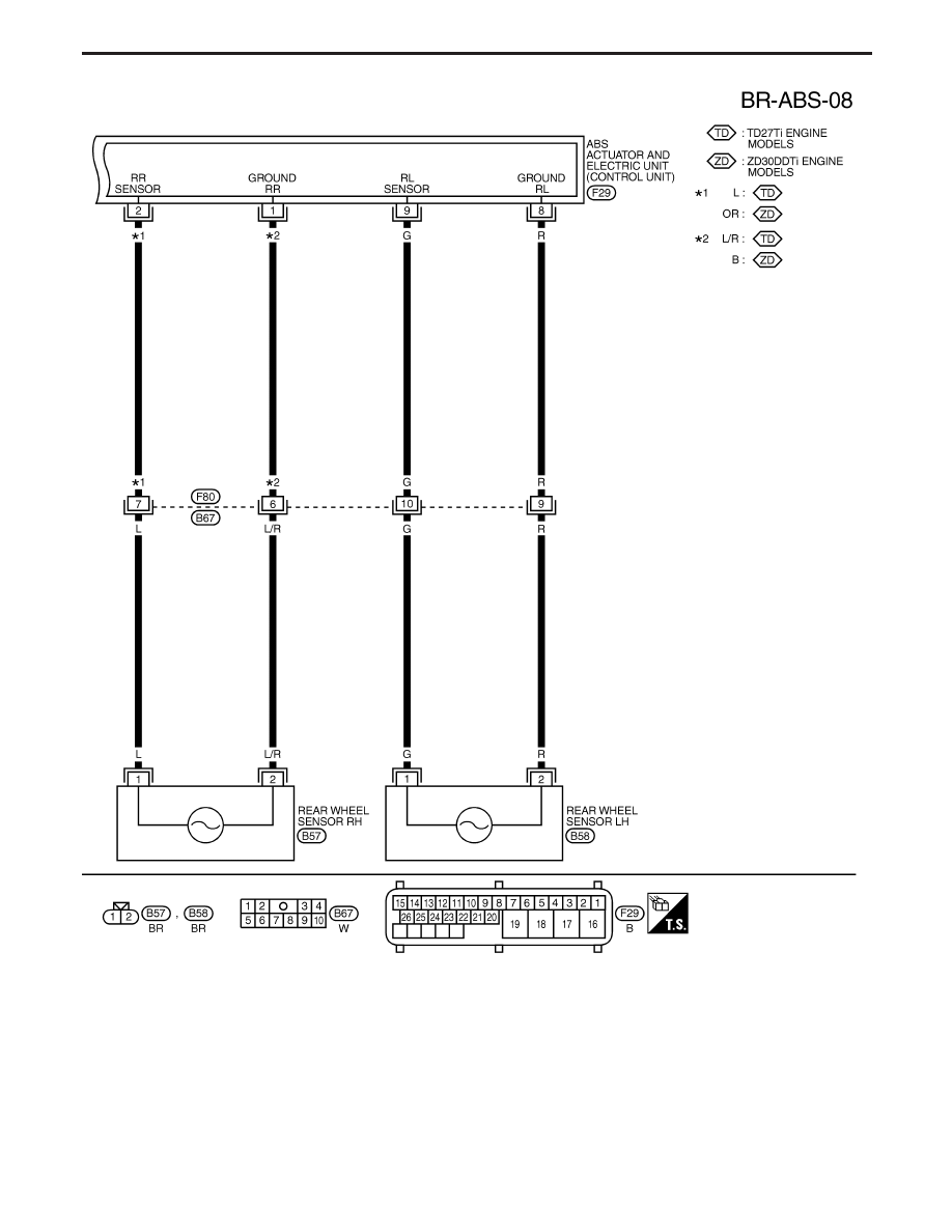
Wiring Diagram — ABS — (Cont’d)

BR-57

CONSULT-II

CONSULT-II APPLICATION TO ABS

ITEM

SELF-DIAGNOSTIC

RESULTS

DATA MONITOR

ACTIVE TEST

Front right wheel sensor

X

X

Front left wheel sensor

X

X

Rear right wheel sensor

X

X

Rear left wheel sensor

X

X

G switch (G sensor)

X

X

X

Stop lamp switch

X

Front right inlet solenoid valve

X

X

X

Front right outlet solenoid valve

X

X

X

Front left inlet solenoid valve

X

X

X

Front left outlet solenoid valve

X

X

X

Rear inlet solenoid valve

X

X

X

Rear outlet solenoid valve

X

X

X

Actuator solenoid valve relay

X

X

Actuator motor relay
(ABS MOTOR is shown on the Data Monitor
screen.)

X

X

X

ABS warning lamp

X

Brake warning lamp

X

Battery voltage

X

X

ABS Operating Signal

X: Applicable
—: Not applicable

ECU (ABS control unit) part number mode

Ignore the ECU part number displayed in the ECU PART NUMBER MODE. Refer to parts catalog to order
the ECU.

TROUBLE DIAGNOSES

BR-58

CONSULT-II Inspection Procedure

SELF-DIAGNOSIS PROCEDURE

1) Turn ignition switch to OFF position.
2) Connect CONSULT-II to Data Link Con-

nector.

1) Start engine.
2) Drive vehicle over 30 km/h (19 MPH)

for at least one minute.

1) Stop vehicle with engine running

and touch “START” on CON-
SULT-II screen.

2) Touch “ABS”.

3) Touch “SELF-DIAG RESULTS”.

I

The screen shows the detected malfunc-
tion and how many times the ignition
switch has been turned since the mal-
function.

Make the necessary repairs following the
diagnostic procedures.

After the malfunctions are repaired, erase
the self-diagnostic results stored in the
control unit by touching “ERASE”.

Check warning lamp(s) for deactivation
after driving vehicle over 30 km/h (19
MPH) for at least one minute.

Test the ABS system in a safe area to
verify that it functions properly.

END

Note: “SELF-DIAG RESULTS” screen shows the detected malfunction and

how many times the ignition switch has been turned since the mal-
function.

YBR265

C2NCS01

C2SSE01

C2SDM01

C2SDR01

H

H

H

H

H

H

H

TROUBLE DIAGNOSES

BR-59

SELF-DIAGNOSTIC RESULTS MODE

Diagnostic item

Diagnostic item is detected when . . .

Diagnostic

procedure

FR RH SENSOR

[OPEN]

I

Circuit for front right wheel sensor is open.
(An abnormally high input voltage is entered.)

4

FR LH SENSOR

[OPEN]

I

Circuit for front left wheel sensor is open.
(An abnormally high input voltage is entered.)

4

RR RH SENSOR

[OPEN]

I

Circuit for rear right sensor is open.
(An abnormally high input voltage is entered.)

4

RR LH SENSOR

[OPEN]

I

Circuit for rear left sensor is open.
(An abnormally high input voltage is entered.)

4

FR RH SENSOR

[SHORT]

I

Circuit for front right wheel sensor is shorted.
(An abnormally low input voltage is entered.)

4

FR LH SENSOR

[SHORT]

I

Circuit for front left wheel sensor is shorted.
(An abnormally low input voltage is entered.)

4

RR RH SENSOR

[SHORT]

I

Circuit for rear right sensor is shorted.
(An abnormally low input voltage is entered.)

4

RR LH SENSOR

[SHORT]

I

Circuit for rear left sensor is shorted.
(An abnormally low input voltage is entered.)

4

ABS SENSOR

[ABNORMAL SIGNAL]

I

Teeth damage on sensor rotor or misalignment of wheel sensor.
(Abnormal wheel sensor signal is entered.)

4

FR RH IN ABS SOL
[OPEN, SHORT]

I

Circuit for front right inlet solenoid valve is open or shorted.
(An abnormally low output voltage is entered.)

3

FR LH IN ABS SOL
[OPEN, SHORT]

I

Circuit for front left inlet solenoid valve is open or shorted.
(An abnormally low output voltage is entered.)

3

FR RH OUT ABS SOL
[OPEN, SHORT]

I

Circuit for front right outlet solenoid valve is open or shorted.
(An abnormally low output voltage is entered.)

3

FR LH OUT ABS SOL
[OPEN, SHORT]

I

Circuit for front left outlet solenoid valve is open or shorted.
(An abnormally low output voltage is entered.)

3

RR IN ABS SOL
[OPEN, SHORT]

I

Circuit for rear right outlet solenoid valve is open or shorted.
(An abnormally high output voltage is entered.)

3

RR OUT ABS SOL
[OPEN, SHORT]

I

Circuit for rear left outlet solenoid valve is open or shorted.
(An abnormally high output voltage is entered.)

3

ABS ACTUATOR RELAY
[ABNORMAL]

I

Actuator solenoid valve relay is ON, even if control unit sends OFF signal.

I

Actuator solenoid valve relay is OFF, even if control unit sends ON signal.

6

ABS MOTOR RELAY
[ABNORMAL]

I

Circuit for ABS motor relay is open or shorted.

I

Circuit for actuator motor is open or shorted.

I

Actuator motor relay is stuck.

5

BATTERY VOLT
[VB-LOW]

I

Power source voltage supplied to ABS control unit is abnormally low.

7

CONTROL UNIT

I

Function of calculation in ABS control unit has failed.

9

G-SENSOR
[ABNORMAL]

I

G sensor is open.

8

If a tire slips on rough roads for more than 10 seconds, the ABS warning lamp may come on. In this case, the malfunctioning code
regarding the wheel sensors may be memorized. Turn off the ignition switch, restart the engine and drive the vehicle at speeds
above 30 km/h (19 MPH).

TROUBLE DIAGNOSES

CONSULT-II Inspection Procedure (Cont’d)

BR-60


Content   ..  63  64  65  66   ..