Nissan Terrano r20e. Manual - part 55
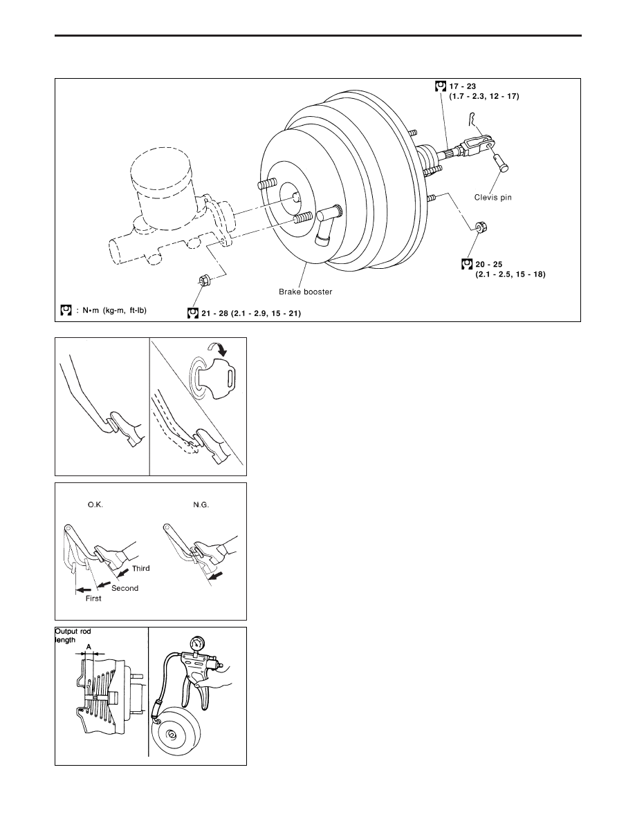
Removal and Installation
Inspection
OPERATING CHECK
I
Depress brake pedal several times with engine off, and check
that there is no change in pedal stroke.
I
Depress brake pedal, then start engine. If pedal goes down
slightly, operation is normal.
AIRTIGHT CHECK
I
Start engine, and stop it after one or two minutes. Depress
brake pedal several times slowly. If pedal goes further down the
first time and gradually rises after second or third time, booster
is airtight.
I
Depress brake pedal while engine is running, and stop engine
with pedal depressed. If there is no change in pedal stroke after
holding pedal down 30 seconds, brake booster is airtight.
OUTPUT ROD LENGTH CHECK
1. Apply vacuum of −66.7 kPa (−667 mbar, −500 mmHg, −19.69
inHg) to brake booster with a manual vacuum pump and check
output rod length “A”.
Specified length “A”:
22.15 - 22.45 mm (0.872 - 0.884 in)
(The length “A” in this case is the distance from end of output
rod to outside of brake booster, when the specified vacuum is
applied.)
YBR259
SBR002A
SBR365A
EBR090
BRAKE BOOSTER
BR-17