Nissan Terrano r20e. Manual - part 54


  Index      Nissan     Nissan Terrano r20e - Service and Repair Manual


Search            


Content   ..  52  53  54  55   ..


Nissan Terrano r20e. Manual - part 54


5. Bleed the air from the rear brake piping.

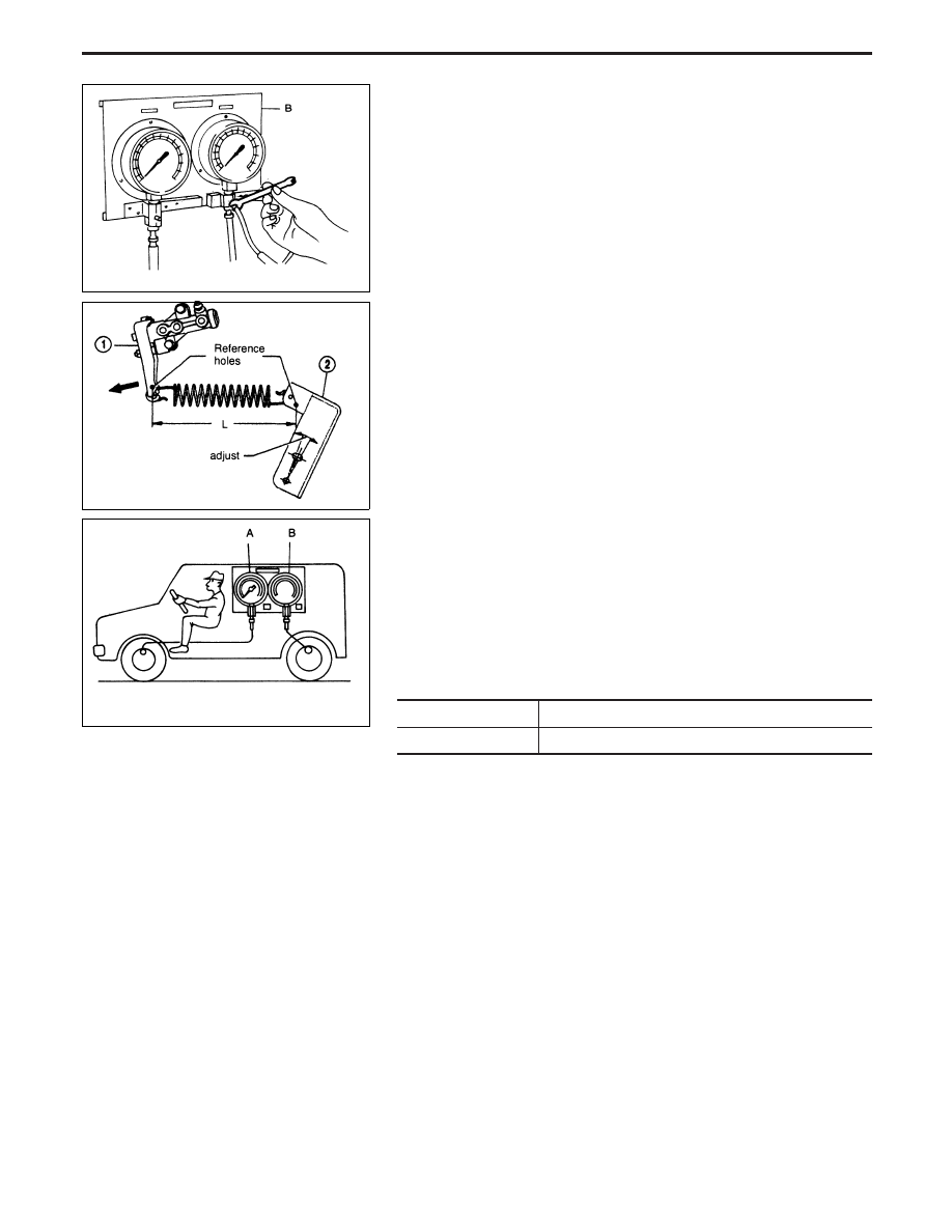
6. To adjust the LSV correctly, proceed as follows:
a. With unladen vehicle (12 liters of fuel, radiator coolant and

engine oil are full). Spare tire, hand tools and mats in desig-
nated positions. Check the length of LSV spring “L”.

b. If the spring length is different from that specified, move the

regulation lever (2) until the specified value is obtained. Move
the LSV lever (1) until it contacts the stopper bolt and recheck
the spring length.

Sensor spring length “L”

Hardtop: 201 mm (7.913 in)
Wagon: 197.5 mm (7.776 in)

NOTE: Do not disturb stopper bolt.

c. Start the engine and run it at idling speed.
d. Slowly depress the brake pedal until an input pressure of 4,805

kPa (48.1 bar, 49 kg/cm

2

, 697 psi) is obtained (at the front axle

pressure gauge) and an output pressure of 1,736 - 2,501 kPa
(18 - 26 bar, 17.7 - 25.5 kg/cm

2

, 252 - 363 psi) is obtained (at

the rear axle pressure gauge).

If the output pressure at the rear axle pressure gauge is not within
the specified values, adjust LSV spring length as described under
b) until the output pressure measured is within the specified range.

Unit: kPa (bar, kg/cm

2

, psi)

Front axle*

4,805 (48.1, 49.0, 697)

Rear axle*

1,736 - 2,501 (18 - 26, 17.7 - 25.5, 252 - 363)

* Load conditions as indicated under 6.a, driver seat occupied.

EBR022

NBR313

EBR026

LOAD SENSING VALVE

Inspection and Adjustment (Cont’d)

BR-13

Removal and Installation

NBR269

BRAKE PEDAL AND BRACKET

BR-14

Inspection

Check brake pedal for following items:

I

Brake pedal bend

I

Clevis pin deformation

I

Crack of any welded portion

I

Crack or deformation of clevis pin stopper

Adjustment

Check brake pedal free height from dash reinforcement panel.

H: Free height

Refer to SDS, BR-85.

D: Full stroke

Refer to SDS, BR-85.

C: Clearance between pedal stopper and threaded end

of stop lamp switch

0.3 - 1.0 mm (0.012 - 0.039 in)

A: Pedal free play

1.0 - 3.0 mm (0.039 - 0.118 in)

If necessary, adjust brake pedal free height.
1. Loosen lock nut and adjust pedal free height by turning brake

booster input rod. Then tighten lock nut.

Make sure that tip of input rod stays inside of clevis as shown.
2. Loosen lock nut and adjust clearance “C” with stop lamp switch.

Then tighten lock nuts.

3. Check pedal free play.
Make sure that stop lamps go off when pedal is released.
4. Check brake system for leaks, accumulation of air or any dam-

age to components (master cylinder, etc.); then make neces-
sary repairs.

SBR997

EBR200

YBR300

BRAKE PEDAL AND BRACKET

BR-15

Removal

CAUTION:

Be careful not to splash brake fluid on painted areas; it may
cause paint damage. If brake fluid is splashed on painted
areas, wash it away with water immediately. DO NOT RUB.
1. Connect a vinyl tube to air bleeder valve.
2. Drain brake fluid from each air bleeder valve, depressing brake

pedal to empty fluid from master cylinder.

3. Remove brake pipe flare nuts.
4. Remove master cylinder mounting nuts.
5. Remove protector of master cylinder, and avoid scratching the

surface of master cylinder during removal.

CAUTION:

Do not disassemble master cylinder.
NOTE:
If it is necessary to change the brake fluid reservoir, remove it
as shown in the illustration on the left, while holding the seals
with one hand.
It is not necessary to replace the seals if they are in a good
condition.

Installation

CAUTION:

I

Refill with new brake fluid “DOT 4”.

I

Never reuse drained brake fluid.

1. Place master cylinder onto brake booster and secure mounting

nuts lightly.

2. Fit flare nuts to master cylinder.
3. Tighten mounting nuts.

: 21 - 29 N

m (2.1 - 3.0 kg-m, 15 - 22 ft-lb)

4. Tighten flare nuts.

: 15 - 18 N

m (1.5 - 1.8 kg-m, 11 - 13 ft-lb)

5. Bleed air. Refer to “Bleeding Brake System”, “BRAKE

HYDRAULIC LINE”, BR-8.

YBR258

EBR080

MASTER CYLINDER

BR-16


Content   ..  52  53  54  55   ..