Nissan Titan. Manual - part 606


  Index      Nissan     Nissan Titan (2014 year) - Service and Repair Manual


Search            


Content   ..  604  605  606  607   ..


Nissan Titan. Manual - part 606


MAIN POWER SUPPLY AND GROUND CIRCUIT

TM-107

< DTC/CIRCUIT DIAGNOSIS >

C

E

F

G

H

I

J

K

L

M

A

B

TM

N

O

P

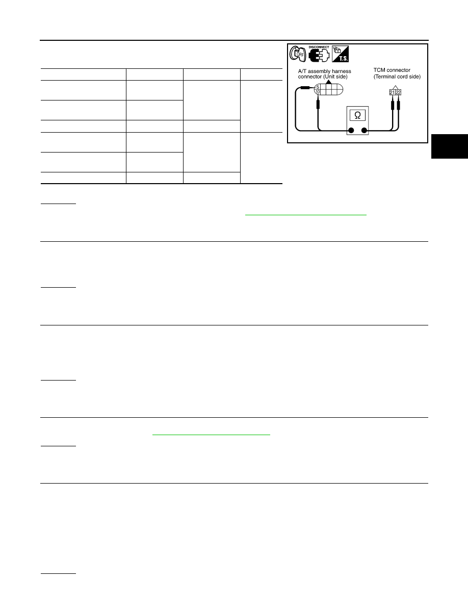
4. Check continuity between A/T assembly harness connector ter-

minals and TCM connector terminals.

5. If OK, check harness for short to ground and short to power.
OK or NG

OK

>> Replace the control valve with TCM. Refer to 

TM-201, "Control Valve with TCM"

.

NG

>> Replace open circuit or short to ground and short to power in harness or connectors.

7.

DETECT MALFUNCTIONING ITEM (STEP 1)

Check the following items:

• Harness for short or open between battery and A/T assembly harness connector terminals 1, 2

• 10A fuse [No. 3, located in the fuse block (J/B)]

• Battery
OK or NG

OK

>> GO TO 2.

NG

>> Repair or replace damaged parts.

8.

DETECT MALFUNCTIONING ITEM (STEP 2)

Check the following items:

• Harness for short or open between ignition switch and A/T assembly harness connector terminal 6

• 10A fuse (No. 49, located in the IPDM E/R)

• IPDM E/R (Ignition relay)

• Ignition switch
OK or NG

OK

>> GO TO 4.

NG

>> Repair or replace damaged parts.

9.

CHECK TCM (TRANSMISSION CONTROL MODULE) RELAY

1. Disconnect TCM relay.

2. Check TCM relay. Refer to 

TM-108, "Component Inspection"

.

OK or NG

OK

>> GO TO 10.

NG

>> Repair or replace damaged parts.

10.

DETECT MALFUNCTIONING ITEM (STEP 3)

Check the following items:

• Harness for short or open between ignition switch and TCM relay harness connector terminal 2

• Harness for short or open between battery and TCM relay harness connector terminal 5

• Harness for open between TCM relay harness connector terminal 1 and ground

• Harness for short or open between TCM relay harness connector terminal 3 and A/T assembly harness con-

nector terminal 6

• 10A fuse [No. 4, located in the fuse block (J/B)] and 10A fuse (No. 49, located in the IPDM E/R)

• IPDM E/R (Ignition relay)

• Ignition switch
OK or NG

Item

 Connector

Terminal

Continuity

A/T assembly harness con-
nector (floor shift)

F9

5

Yes

A/T assembly harness con-
nector (column shift)

F17

TCM connector 

F504

21

A/T assembly harness con-
nector (floor shift)

F9

10

Yes

A/T assembly harness con-
nector (column shift)

F17

TCM connector 

F504

22

SCIA5465E

TM-108

< DTC/CIRCUIT DIAGNOSIS >

MAIN POWER SUPPLY AND GROUND CIRCUIT

OK

>> GO TO 4.

NG

>> Repair or replace damaged parts.

Component Inspection

INFOID:0000000009885867

1.

TCM (TRANSMISSION CONTROL MODULE) RELAY

Check the continuity between TCM relay terminals as per the follow-

ing conditions.

OK or NG

OK

>> INSPECTION END

NG

>> Replace the TCM relay.

+

Conditions

Continuity

TCM relay

Terminal

3

5

12 V direct current supply be-
tween terminals 1 and 2

Yes

No current supply

No

PBIB0098E

CLOSED THROTTLE POSITION AND WIDE OPEN THROTTLE POSITION CIR-

CUIT

TM-109

< DTC/CIRCUIT DIAGNOSIS >

C

E

F

G

H

I

J

K

L

M

A

B

TM

N

O

P

CLOSED THROTTLE POSITION AND WIDE OPEN THROTTLE POSITION
CIRCUIT

CONSULT Reference Value in Data Monitor Mode

INFOID:0000000009885868

Diagnosis Procedure

INFOID:0000000009885869

1.

CHECK CAN COMMUNICATION LINE

Perform the self-diagnosis. Refer to 

TM-38, "CONSULT Function (TRANSMISSION)"

.

Is a malfunction in the CAN communication indicated in the results?

YES

>> Check CAN communication line. Refer to 

TM-48

.

NO

>> GO TO 2.

2.

CHECK THROTTLE POSITION SIGNAL CIRCUIT

With CONSULT

1. Turn ignition switch “ON”. (Do not start engine.)

2. Select “ECU INPUT SIGNALS” in “DATA MONITOR” mode for “TRANSMISSION” with CONSULT.

3. Depress accelerator pedal and read out the value of “CLSD THL POS” and “W/O THL POS”.

OK or NG

OK

>> INSPECTION END

NG

>> Check the following items. If NG, repair or replace damaged parts.

• Perform the self-diagnosis for “ENGINE” with CONSULT.

• Open circuit or short to ground or short to power in harness or connectors.

• Pin terminals for damage or loose connection with harness connector.

Item name

Condition 

Display value

CLSD THL POS

Released accelerator pedal.

ON

Fully depressed accelerator pedal.

OFF

W/O THL POS

Fully depressed accelerator pedal.

ON

Released accelerator pedal.

OFF

Accelerator Pedal Operation

Monitor Item

CLSD THL POS

W/O THL POS

Released

ON

OFF

Fully depressed

OFF

ON

TM-110

< DTC/CIRCUIT DIAGNOSIS >

BRAKE SIGNAL CIRCUIT

BRAKE SIGNAL CIRCUIT

CONSULT Reference Value in Data Monitor Mode

INFOID:0000000009885870

Diagnosis Procedure

INFOID:0000000009885871

1.

CHECK CAN COMMUNICATION LINE

Perform the self-diagnosis. Refer to 

TM-38, "CONSULT Function (TRANSMISSION)"

.

Is a malfunction in the CAN communication indicated in the results?

YES

>> Check CAN communication line. Refer to 

TM-48, "Diagnosis Procedure"

.

NO

>> GO TO 2.

2.

CHECK STOP LAMP SWITCH CIRCUIT

With CONSULT

1. Turn ignition switch “ON”. (Do not start engine.)

2. Select “ECU INPUT SIGNALS” in “DATA MONITOR” mode for “TRANSMISSION” with CONSULT.

3. Read out ON/OFF switching action of the “BRAKE SW”.
OK or NG

OK

>> INSPECTION END

NG

>> • Column shift models, GO TO 3

• Floor shift models, GO TO 4

3.

CHECK STOP LAMP SWITCH (COLUMN SHIFT MODELS)

Check continuity between stop lamp switch terminals 3 and 4.

Check stop lamp switch after adjusting brake pedal — refer to

BR-13, "Inspection and Adjustment - Standard Pedal"

 or 

BR-14,

"Inspection and Adjustment - Adjustable Pedal"

.

OK or NG

OK

>> Check stop lamp switch circuit.

NG

>> Repair or replace stop lamp switch.

4.

CHECK STOP LAMP SWITCH (FLOOR SHIFT MODELS)

Check continuity between stop lamp switch terminals 1 and 2.

Check stop lamp switch after adjusting brake pedal — refer to

BR-13, "Inspection and Adjustment - Standard Pedal"

 or 

BR-14,

"Inspection and Adjustment - Adjustable Pedal"

.

OK or NG

OK

>> Check stop lamp switch circuit.

NG

>> Repair or replace stop lamp switch.

Item name

Condition 

Display value

BRAKE SW

Depressed brake pedal.

ON

Released brake pedal.

OFF

Condition

Continuity

When brake pedal is depressed

Yes

When brake pedal is released

No

AWDIA0419ZZ

Condition

Continuity

When brake pedal is depressed

Yes

When brake pedal is released

No

PBIB0118E


Content   ..  604  605  606  607   ..