Nissan Titan. Manual - part 585


  Index      Nissan     Nissan Titan (2014 year) - Service and Repair Manual


Search            


Content   ..  583  584  585  586   ..


Nissan Titan. Manual - part 585


A/T CONTROL SYSTEM

TM-23

< SYSTEM DESCRIPTION >

C

E

F

G

H

I

J

K

L

M

A

B

TM

N

O

P

TCM Function

INFOID:0000000009885684

The function of the TCM is to:

• Receive input signals sent from various switches and sensors.

• Determine required line pressure, shifting point, lock-up operation, and engine brake operation.

• Send required output signals to the respective solenoids.

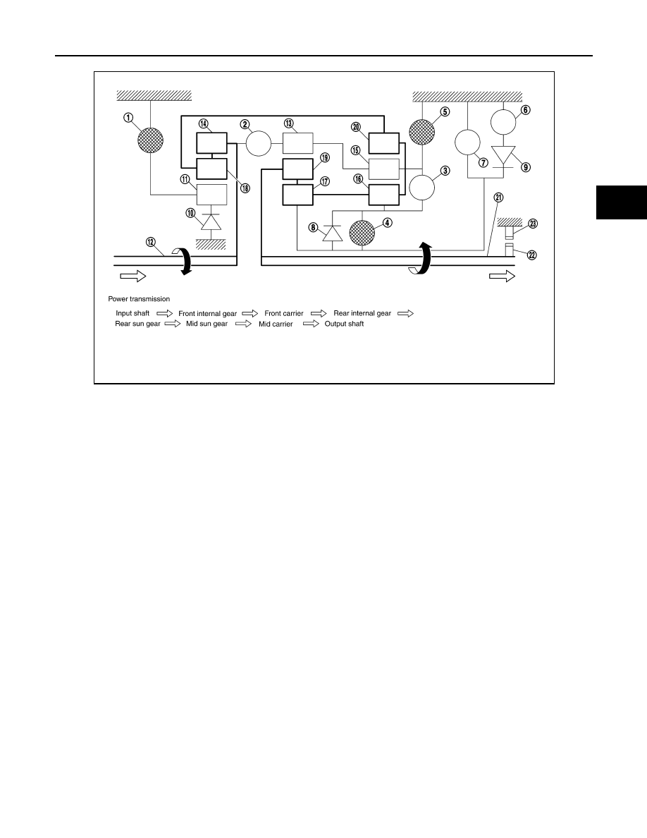
CONTROL SYSTEM OUTLINE 

The automatic transmission senses vehicle operating conditions through various sensors or signals. It always

controls the optimum shift position and reduces shifting and lock-up shocks.

1.

Front brake

2.

 Input clutch

3.

Direct clutch

4.

High and low reverse clutch

5.

Reverse brake

6.

Forward brake

7.

Low coast brake

8.

1st one-way clutch

9.

Forward one-way clutch

10. 3rd one-way clutch

11. Front sun gear

12. Input shaft

13. Mid internal gear

14. Front internal gear

15. Rear carrier

16. Rear sun gear

17. Mid sun gear

18. Front carrier

19.  Mid carrier

20. Rear internal gear

21. Output shaft

22. Parking gear

23. Parking pawl

SCIA1519E

TM-24

< SYSTEM DESCRIPTION >

A/T CONTROL SYSTEM

*1: Floor shift models
*2: Column shift models

CONTROL SYSTEM DIAGRAM 

Floor Shift Models

SENSORS (or SIGNALS)

TCM

ACTUATORS

Transmission range switch
Accelerator pedal position sensor
Closed throttle position signal
Wide open throttle position signal
Engine speed signal
A/T fluid temperature sensor
Output speed sensor
Vehicle speed signal
Manual mode switch signal

*2

Stop lamp switch signal
Input speed sensor
1st position switch signal

*1

4th position switch signal

*1

ATF pressure switch 2 signal
Tow mode switch signal

Shift control
Line pressure control
Lock-up control
Engine brake control
Timing control
Fail-safe control
Self-diagnosis
CONSULT communication line
Duet-EA control
CAN system

Input clutch solenoid valve 
Direct clutch solenoid valve 
Front brake solenoid valve
High and low reverse clutch sole-
noid valve
Low coast brake solenoid valve
Torque converter clutch solenoid 
valve
Line pressure solenoid valve
A/T CHECK indicator lamp
Starter relay
Back-up lamp relay

JSDIA1985GB

A/T CONTROL SYSTEM

TM-25

< SYSTEM DESCRIPTION >

C

E

F

G

H

I

J

K

L

M

A

B

TM

N

O

P

Column Shift Models

CAN Communication

INFOID:0000000009885685

SYSTEM DESCRIPTION

CAN (Controller Area Network) is a serial communication line for real time application. It is an on-vehicle mul-

tiplex communication line with high data communication speed and excellent error detection ability. Many elec-

tronic control units are equipped onto a vehicle, and each control unit shares information and links with other

control units during operation (not independent). In CAN communication, control units are connected with 2

communication lines (CAN H line, CAN L line) allowing a high rate of information transmission with less wiring.

Each control unit transmits/receives data but selectively reads required data only. For details, refer to 

LAN-46,

"CAN System Specification Chart"

.

JSDIA1986GB

TM-26

< SYSTEM DESCRIPTION >

A/T CONTROL SYSTEM

Input/Output Signal of TCM

INFOID:0000000009885686

*1: Spare for output speed sensor.
*2: Spare for accelerator pedal position signal.
*3: If these input and output signals are different, the TCM triggers the fail-safe function.
*4: CAN communications.
*5: Used as a condition for starting self-diagnostics; If self-diagnostics are not started, it is judged that there is some kind of error.

Line Pressure Control

INFOID:0000000009885687

• When an input torque signal equivalent to the engine drive force is sent from the ECM to the TCM, the TCM

controls the line pressure solenoid.

Control item

Line

pressure

control

Vehicle 

speed 

control

Shift     

control

Lock-up 

control

Engine 

brake 

control

Fail-safe 

function 

(*3)

Self-diag-

nostics 

function

Input

Accelerator pedal position signal 

(*4)

X

X

X

X

X

X

X

Output speed sensor

X

X

X

X

X

X

Vehicle speed signal

(*1) (*4)

X

X

X

X

X

Closed throttle position signal

(*4)

(*2) X

(*2) X

X

(*2) X

(*5) X

Wide open throttle position signal

(*4)

(*2) X

(*2) X

(*2) X

(*5) X

Input speed sensor 1

X

X

X

X

X

Input speed sensor 2
(for 4th speed only)

X

X

X

X

X

Engine speed signals

(*4)

X

X

Transmission  range  switch

X

X

X

X

X

X

X

Stop lamp switch signal

(*4)

X

X

X

(*5)  X

A/T fluid temperature sensor

X

X

X

X

X

X

X

ASCD

Operation signal

(*4)

X

X

X

X

Overdrive cancel sig-
nal

(*4)

X

X

X

TCM power supply voltage signal

X

X

X

X

X

X

Out-
put

Direct clutch solenoid

X

X

X

X

Input clutch solenoid

X

X

X

X

High and low reverse clutch sole-
noid

X

X

X

X

Front brake solenoid

X

X

X

X

Low coast brake solenoid (ATF 
pressure switch 2)

X

X

X

X

X

Line  pressure  solenoid

X

X

X

X

X

X

X

TCC solenoid

X

X

X

Starter relay

X

X


Content   ..  583  584  585  586   ..