Nissan Titan. Manual - part 582


  Index      Nissan     Nissan Titan (2014 year) - Service and Repair Manual


Search            


Content   ..  580  581  582  583   ..


Nissan Titan. Manual - part 582


A/T CONTROL SYSTEM

TM-11

< SYSTEM DESCRIPTION >

C

E

F

G

H

I

J

K

L

M

A

B

TM

N

O

P

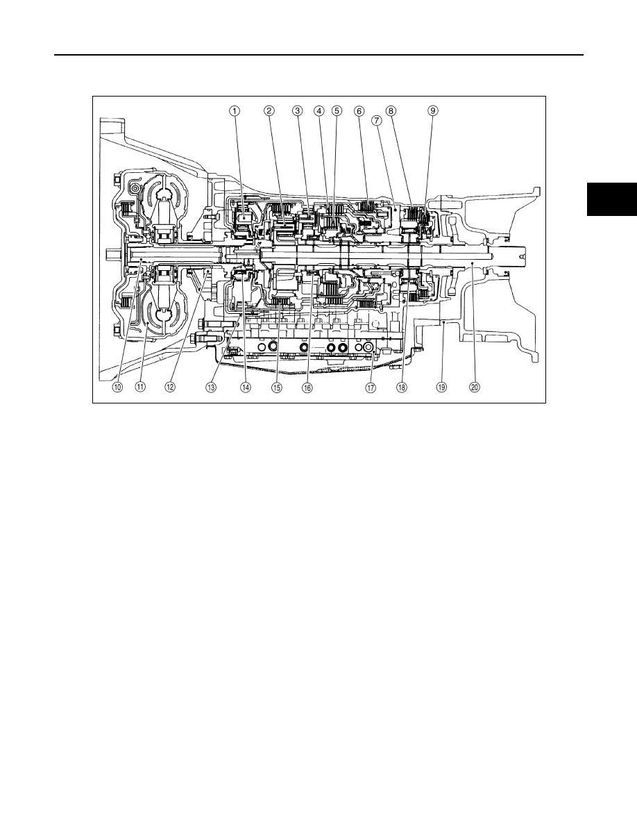
Cross-Sectional View (4WD models)

INFOID:0000000009885682

Shift Mechanism

INFOID:0000000009885683

The automatic transmission uses compact dual planetary gear systems to improve power-transmission effi-

ciency, simplify construction and reduce weight.

It also employs an optimum shift control and super wide gear ratios. They improve starting performance and

acceleration during medium and high-speed operation.

CONSTRUCTION 

1.

Front planetary gear

2.

Mid planetary gear

3.

Rear planetary gear

4.

Direct clutch

5.

High & low reverse clutch

6.

Reverse brake

7.

Drum support

8.

Forward brake

9.

Low coast brake

10. Input shaft

11. Torque converter

12. Oil pump

13. Front brake

14. 3rd one-way clutch

15. Input clutch

16. 1st one-way clutch

17. Control valve with TCM

18. Forward one-way clutch

19. Adapter case

20.  Output shaft

SCIA5268E

TM-12

< SYSTEM DESCRIPTION >

A/T CONTROL SYSTEM

FUNCTION OF CLUTCH AND BRAKE 

CLUTCH AND BAND CHART (FLOOR SHIFT MODELS)

1.

Front brake

2.

Input clutch

3.

Direct clutch

4.

High and low reverse clutch

5.

Reverse brake

6.

Forward brake

7.

Low coast brake

8.

1st one-way clutch

 9.

Forward one-way clutch

10. 3rd one-way clutch

11. Front sun gear

12. Input shaft

 
13.

Mid internal gear

14. Front internal gear

15. Rear carrier

16. Rear sun gear

17. Mid sun gear

18. Front carrier

19. Mid carrier

20. Rear internal gear

21. Output shaft 

22. Parking gear

23. Parking pawl

PCIA0002J

Name of the Part

Abbreviation

Function

Front brake (1)

FR/B

Fastens the front sun gear (11).

 Input clutch (2)

I/C

Connects the input shaft (12), the front internal gear (14) and the mid internal 
gear (13).

Direct clutch (3)

D/C

Connects the rear carrier (15) and the rear sun gear (16).

High and low reverse clutch (4)

HLR/C

Connects the mid sun gear (17) and the rear sun gear (16).

Reverse brake (5)

R/B

Fastens the rear carrier (15).

Forward brake (6)

F/B

Fastens the mid sun gear (17).

Low coast brake (7) 

LC/B

Fastens the mid sun gear (17).

1st one-way clutch (8)

1st/O.C

Allows the rear sun gear (16) to turn freely forward relative to the mid sun gear 
(17) but fastens it for reverse rotation.

Forward one-way clutch (9)

F/O.C

Allows the mid sun gear (17) to turn freely in the forward direction but fastens it 
for reverse rotation.

3rd one-way clutch (10)

3rd/O.C 

Allows the front sun gear (11) to turn freely in the forward direction but fastens 
it for reverse rotation.

Shift position

I/C

HLR/C

D/C

R/B

FR/B

LC/B

Fwd/B

1st 

OWC

Fwd 

OWC

3rd 

OWC

Remarks

P

PARK POSITION

R

REVERSE PO-

SITION

A/T CONTROL SYSTEM

TM-13

< SYSTEM DESCRIPTION >

C

E

F

G

H

I

J

K

L

M

A

B

TM

N

O

P

—Operates

—Operates during “progressive” acceleration.

—Operates and effects power transmission while coasting.

—Line pressure is applied but does not affect power transmission.

—Operates under conditions shown in HLR/C Operating Condition

—Operates under conditions shown in LC/B Operating Condition. Delay control is applied during D (4,3,2,1) 

⇒N shift.

CLUTCH AND BAND CHART (COLUMN SHIFT MODELS)

N

NEUTRAL POSI-

TION

D

1st

Automatic shift

1

⇔2⇔3⇔4⇔5

2nd

3rd

4th

5th

4

1st

Automatic shift

1

⇔2⇔3⇔4

2nd

3rd

4th

3

1st

Automatic shift

1

⇔2⇔3⇐4

2nd

3rd

4th

2

1st

Automatic shift

1

⇔2⇐3⇐4

2nd

3rd

4th

1

1st

Locks (held sta-

tionary in 1GR)

1

⇐2⇐3⇐4

2nd

3rd

4th

Shift position

I/C

HLR/C

D/C

R/B

FR/B

LC/B

Fwd/B

1st 

OWC

Fwd 

OWC

3rd 

OWC

Remarks

SCIA5642E

TM-14

< SYSTEM DESCRIPTION >

A/T CONTROL SYSTEM

—Operates

—Operates during “progressive” acceleration.

—Operates and effects power transmission while coasting.

—Line pressure is applied but does not affect power transmission.

—Operates under conditions shown in HLR/C Operating Condition

—Operates under conditions shown in LC/B Operating Condition. Delay control is applied during D (4,3,2,1) 

⇒N shift.

Shift position

I/C

HLR/C

D/C

R/B

FR/B

LC/B

Fwd/B

1st 

OWC

Fwd 

OWC

3rd 

OWC

Remarks

P

PARK POSITION

R

REVERSE PO-

SITION

N

NEUTRAL POSI-

TION

D

1st

Automatic shift

1

⇔2⇔3⇔4⇔5

2nd

3rd

4th

5th

M5

1st

Automatic shift

1

⇔2⇔3⇔4⇔5

2nd

3rd

4th

5th

M4

1st

Automatic shift

1

⇔2⇔3⇔4

2nd

3rd

4th

M3

1st

Automatic shift

1

⇔2⇔3

2nd

3rd

M2

1st

Automatic shift

1

⇔2

2nd

M1

1st

Locks (held sta-

tionary in 1GR)

2nd


Content   ..  580  581  582  583   ..