Nissan Titan. Manual - part 569


  Index      Nissan     Nissan Titan (2014 year) - Service and Repair Manual


Search            


Content   ..  567  568  569  570   ..


Nissan Titan. Manual - part 569


ST-12

< UNIT REMOVAL AND INSTALLATION >

HYDRAULIC LINE

Installation is in the reverse order of removal.

CAUTION:

Do not reuse O-rings.

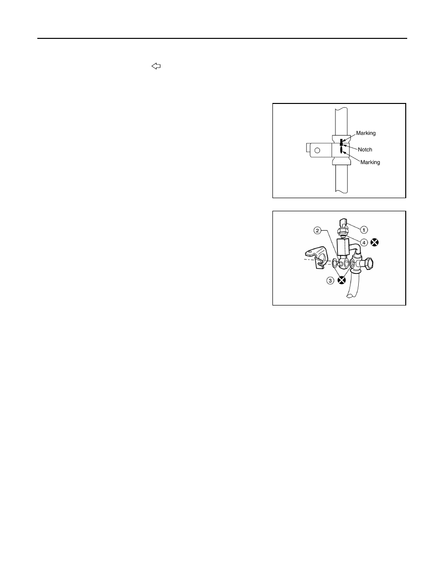
• Confirm mating marks are aligned with hose and clamp, then cor-

rect if needed.

• To install eye joint, align projection (2) of eye joint with notch of

power steering pump, and attach eye joint to power steering pump

properly. Tighten eye bolt by hand fully, then torque to specifica-

tion.

(1) Pressure sensor

(3) Copper sealing washers

(4) O-ring

CAUTION:

Do not reuse O-rings or copper sealing washers.

7.

Eye bolt

8.

O-ring

9.

Power steering pressure sensor

10

O-ring

A.

Power steering reservoir attachment

B.

Power steering pump connection

C.

Steering gear connections

Front

SGIA0563E

ALGIA0102ZZ

POWER STEERING OIL PUMP

ST-13

< UNIT REMOVAL AND INSTALLATION >

C

D

E

F

H

I

J

K

L

M

A

B

ST

N

O

P

POWER STEERING OIL PUMP

Removal and Installation

INFOID:0000000009883508

NOTE:

When removing components such as hoses, tubes/lines, etc., cap or plug openings to prevent fluid from spill-

ing.

REMOVAL

1. Drain power steering fluid from reservoir tank.
2. Remove engine room cover. Refer to 

EM-25, "Removal and Installation"

.

3. Remove air duct assembly. Refer to 

VTL-25, "Removal and Installation"

.

4. Remove power steering reservoir tank.
5. Remove serpentine drive belt from auto tensioner and power steering oil pump. Refer to 

EM-14,

"Removal and Installation"

.

6. Disconnect pressure sensor electrical connector.
7. Remove high pressure and low pressure piping and copper sealing washers from power steering oil

pump. Refer to 

ST-11

.

CAUTION:

Do not reuse copper sealing washers.

8. Remove bolts, then remove power steering oil pump.

INSTALLATION

1.

Pulley

2.

Engine bracket

3.

Bracket

4.

Bracket nut

5.

Suction hose

6.

Power steering pump

A.

Refer to 

ST-11, "Removal and In-

stallation"

.

B.

High pressure hose

ALGIA0152ZZ

ST-14

< UNIT REMOVAL AND INSTALLATION >

POWER STEERING OIL PUMP

Installation is in the reverse order of removal. Refer to 

ST-13

 for tightening torque.

• After installation, bleed air. Refer to 

BR-16, "Bleeding Brake System"

.

CAUTION:

Do not reuse copper sealing washers.

NOTE:

Belt tension is automatic and requires no adjustment.

POWER STEERING GEAR AND LINKAGE

ST-15

< UNIT REMOVAL AND INSTALLATION >

C

D

E

F

H

I

J

K

L

M

A

B

ST

N

O

P

POWER STEERING GEAR AND LINKAGE

Removal and Installation

INFOID:0000000009883509

CAUTION:

Spiral cable may snap due to steering operation if steering column is separated from steering gear

assembly. Therefore secure steering wheel to avoid turning.

NOTE:

When removing components such as hoses, tubes/lines, etc., cap or plug openings to prevent fluid from spill-

ing.

REMOVAL

1. Turn wheels to the straight-ahead position.
2. Remove both front wheels and tires from vehicle using power tool.
3. Remove engine under cover or skid plate (if equipped). Refer to 

EXT-15, "Removal and Installation"

.

4. On 4WD model, remove front final drive, then support drive shafts with wire. Refer to 

DLN-167, "Removal

and Installation"

.

5. Remove cotter pin at steering outer socket and discard, then loosen nut.
6. Remove steering outer socket from steering knuckle using suitable tool. Be careful not to damage ball

joint boot.

CAUTION:

Temporarily tighten nut to prevent damage to threads and to prevent Tool from coming off.

7. On 2WD model, remove stabilizer bar bolts and reposition stabilizer bar. Refer to 

FSU-12, "Removal and

Installation"

.

8. Remove oil piping (high pressure side and low pressure side)

and O-ring from steering gear assembly, then drain fluid from

piping.

CAUTION:

Do not reuse O-ring.

1.

Cotter pin

2.

Power steering gear bracket

3.

Power steering gear insulator

4.

Power steering gear assembly

5.

Washer

Front

AWGIA0234ZZ

LGIA0032E


Content   ..  567  568  569  570   ..