Nissan Titan. Manual - part 388


  Index      Nissan     Nissan Titan (2014 year) - Service and Repair Manual


Search            


Content   ..  386  387  388  389   ..


Nissan Titan. Manual - part 388


AMBIENT SENSOR

HAC-57

< DTC/CIRCUIT DIAGNOSIS >

[AUTOMATIC AIR CONDITIONER]

C

D

E

F

G

H

J

K

L

M

A

B

HAC

N

O

P

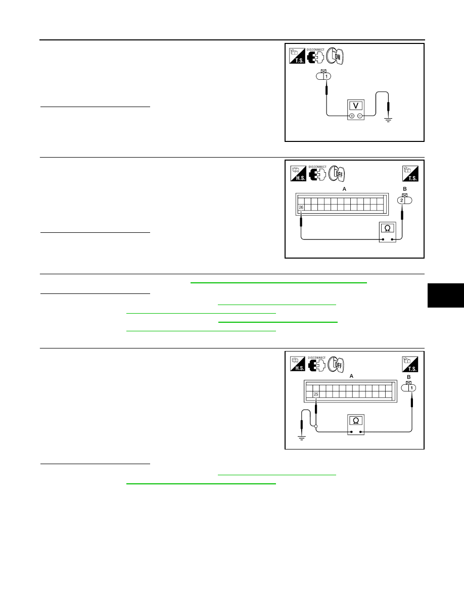
1. Disconnect ambient sensor connector.

2. Turn ignition switch ON.

3. Check voltage between ambient sensor harness connector E1

terminal 1 and ground.

Is the inspection result normal?

YES

>> GO TO 2.

NO

>> GO TO 4.

2.

CHECK CIRCUIT CONTINUITY BETWEEN AMBIENT SENSOR AND FRONT AIR CONTROL 

1. Turn ignition switch OFF.

2. Disconnect front air control connector.

3. Check continuity between ambient sensor harness connector

E1 (B) terminal 2 and front air control harness connector M49

(A) terminal 26.

Is the inspection result normal?

YES

>> GO TO 3.

NO

>> Repair harness or connector.

3.

CHECK AMBIENT SENSOR

Check the ambient sensor circuit. Refer to 

HAC-57, "Ambient Sensor Component Inspection"

.

Is the inspection result normal?

YES

>> 1. Replace front air control. Refer to 

VTL-8, "Removal and Installation"

.

2. GO TO 

HAC-21, "Front Air Control Self-Diagnosis"

 and perform self-diagnosis.

NO

>> 1. Replace ambient sensor. Refer to 

HA-45, "Removal and Installation"

.

2. GO TO 

HAC-21, "Front Air Control Self-Diagnosis"

 and perform self-diagnosis.

4.

CHECK CIRCUIT CONTINUITY BETWEEN AMBIENT SENSOR AND FRONT AIR CONTROL

1. Turn ignition switch OFF.

2. Disconnect front air control connector.

3. Check continuity between ambient sensor harness connector

E1 (B) terminal 1 and front air control harness connector M49

(A) terminal 25.

4. Check continuity between ambient sensor harness connector

E1 (B) terminal 2 and ground.

Is the inspection result normal?

YES

>> 1. Replace front air control. Refer to 

VTL-8, "Removal and Installation"

.

2. GO TO 

HAC-21, "Front Air Control Self-Diagnosis"

 and perform self-diagnosis.

NO

>> Repair harness or connector.

Ambient Sensor Component Inspection

INFOID:0000000009882473

COMPONENT INSPECTION

Ambient Sensor

1 - Ground

: Approx. 5V

AWIIA0161ZZ

2 - 26

: Continuity should exist.

AWIIA1039ZZ

1 - 25

: Continuity should exist.

1 - Ground

: Continuity should not exist.

AWIIA1040ZZ

HAC-58

< DTC/CIRCUIT DIAGNOSIS >

[AUTOMATIC AIR CONDITIONER]

AMBIENT SENSOR

After disconnecting ambient sensor (1) connector E1, measure

resistance between terminals 1 and 2 at sensor component side,

using the table below.

If NG, replace ambient sensor. Refer to 

HA-45, "Removal and Instal-

lation"

.

Temperature 

°C (°F)

Resistance k

−15 (5)

12.73

−10 (14)

9.92

−5 (23)

7.80

0 (32)

6.19

5 (41)

4.95

10 (50)

3.99

15 (59)

3.24

20 (68)

2.65

25 (77)

2.19

30 (86)

1.81

35 (95)

1.51

40 (104)

1.27

45 (113)

1.07

AWIIA1080ZZ

IN-VEHICLE SENSOR

HAC-59

< DTC/CIRCUIT DIAGNOSIS >

[AUTOMATIC AIR CONDITIONER]

C

D

E

F

G

H

J

K

L

M

A

B

HAC

N

O

P

IN-VEHICLE SENSOR

Component Description

INFOID:0000000009882474

COMPONENT DESCRIPTION

In-vehicle Sensor

The in-vehicle sensor (1) is located on the lower instrument panel

LH. It converts variations in temperature of passenger compartment

air (drawn in through the integrated fan) into a resistance value. It is

then input into the front air control.

In-Vehicle Sensor Diagnosis Procedure

INFOID:0000000009882475

Regarding Wiring Diagram information, refer to 

HAC-71, "Wiring Diagram - Automatic Air Conditioner"

.

DIAGNOSTIC PROCEDURE FOR IN-VEHICLE SENSOR

SYMPTOM: In-vehicle sensor circuit is open or shorted. Using the

CONSULT, DTC B2578 or B2579 is displayed. Without a CONSULT,

code 30, 31 is indicated on front air control as a result of conducting

self-diagnosis.

1.

CHECK IN-VEHICLE SENSOR CIRCUIT

Is self-diagnosis DTC B2578 or B2579 (with CONSULT) or code 30, 31 (without CONSULT) present?
YES or NO?

YES

>> GO TO 6.

NO

>> GO TO 2.

2.

CHECK VOLTAGE BETWEEN IN-VEHICLE SENSOR AND GROUND

AWIIA0425ZZ

AWIIA0165ZZ

AWIIA0426GB

HAC-60

< DTC/CIRCUIT DIAGNOSIS >

[AUTOMATIC AIR CONDITIONER]

IN-VEHICLE SENSOR

1. Disconnect in-vehicle sensor connector.

2. Turn ignition switch ON.

3. Check voltage between in-vehicle sensor harness connector

M32 terminal 4 and ground.

Is the inspection result normal?

YES

>> GO TO 3.

NO

>> GO TO 5.

3.

CHECK CIRCUIT CONTINUITY BETWEEN IN-VEHICLE SENSOR AND FRONT AIR CONTROL

1. Turn ignition switch OFF.

2. Disconnect front air control connector M49.

3. Check continuity between in-vehicle sensor harness connector

M32 (B) terminal 1 and front air control harness connector M49

(A) terminal 26.

Is the inspection result normal?

YES

>> GO TO 4.

NO

>> Repair harness or connector.

4.

CHECK IN-VEHICLE SENSOR

Check in-vehicle sensor. Refer to 

HAC-61, "In-Vehicle Sensor Component Inspection"

.

Is the inspection result normal?

YES

>> 1. Replace front air control. Refer to 

VTL-8, "Removal and Installation"

.

2. Go to 

HAC-21, "Front Air Control Self-Diagnosis"

 and perform self-diagnosis.

NO

>> 1. Replace in-vehicle sensor. Refer to 

VTL-9, "Removal and Installation"

.

2. Go to 

HAC-21, "Front Air Control Self-Diagnosis"

 and perform self-diagnosis.

5.

CHECK CIRCUIT CONTINUITY BETWEEN IN-VEHICLE SENSOR AND FRONT AIR CONTROL

1. Turn ignition switch OFF.

2. Disconnect front air control connector.

3. Check continuity between in-vehicle sensor harness connector

M32 (B) terminal 4 and front air control harness connector M50

(A) terminal 32.

4. Check continuity between in-vehicle sensor harness connector

M32 (B) terminal 4 and ground.

Is the inspection result normal?

YES

>> 1. Replace front air control. Refer to 

VTL-8, "Removal and Installation"

.

2. Go to 

HAC-21, "Front Air Control Self-Diagnosis"

 and perform self-diagnosis.

NO

>> Repair harness or connector.

6.

CHECK CIRCUIT CONTINUITY BETWEEN IN-VEHICLE SENSOR MOTOR AND FRONT AIR CONTROL

(SELF-DIAGNOSIS CODES 30, 31, 44, 46 OR DTC B2578, B2579)

4 - Ground

: Approx. 5V.

LJIA0089E

1 - 26

: Continuity should exist.

AWIIA0427ZZ

4 - 32

: Continuity should exist.

4 - Ground

Continuity should not exist.

AWIIA0428ZZ


Content   ..  386  387  388  389   ..