Nissan Titan. Manual - part 387


  Index      Nissan     Nissan Titan (2014 year) - Service and Repair Manual


Search            


Content   ..  385  386  387  388   ..


Nissan Titan. Manual - part 387


MAGNET CLUTCH

HAC-53

< DTC/CIRCUIT DIAGNOSIS >

[AUTOMATIC AIR CONDITIONER]

C

D

E

F

G

H

J

K

L

M

A

B

HAC

N

O

P

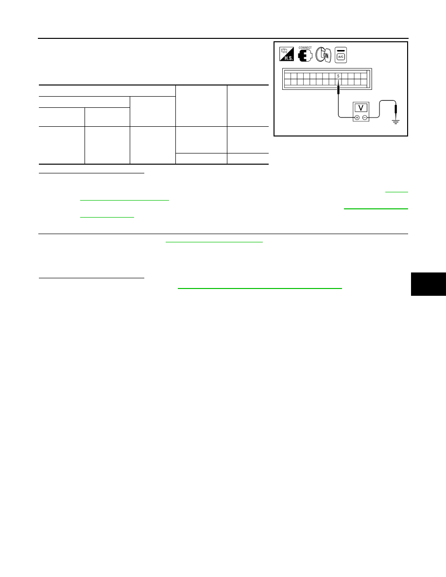
1. Reconnect BCM connector and front air control connector.

2. Turn ignition switch ON.

3. Check voltage between front air control harness connector M49

terminal 5 and ground.

Is the inspection result normal?

YES

>> GO TO 12.

NO-1 >> If the voltage is approx. 5V when blower motor is ON, replace front air control. Refer to 

VTL-8,

"Removal and Installation"

.

NO-2 >> If the voltage is approx. 0V when blower motor is OFF, replace BCM. Refer to 

BCS-52, "Removal

and Installation"

.

12.

CHECK CAN COMMUNICATION

Check CAN communication. Refer to 

LAN-4, "System Description"

.

• BCM  –  ECM

• ECM – IPDM E/R

• ECM – Front air control
Is the inspection result normal?

YES

>> Replace IPDM E/R. Refer to 

PCS-28, "Removal and Installation of IPDM E/R"

.

NO

>> Repair or replace malfunctioning part(s).

Terminals

Condition

Voltage

(+)

(-)

Front air con-

trol connector

Terminal No.

M49

5

Ground

A/C switch: ON
Blower motor 
operates

Approx. 0V

A/C switch: OFF

Approx. 5V

AWIIA0419ZZ

HAC-54

< DTC/CIRCUIT DIAGNOSIS >

[AUTOMATIC AIR CONDITIONER]

WATER VALVE CIRCUIT

WATER VALVE CIRCUIT

Description

INFOID:0000000009882469

COMPONENT DESCRIPTION

Water Valve

The water valve (1) cuts the flow of engine coolant to the heater core

to allow for maximum cooling during A/C operation. It is controlled by

the front air control.

Water Valve Diagnosis Procedure

INFOID:0000000009882470

Regarding Wiring Diagram information, refer to 

HAC-71, "Wiring Diagram - Automatic Air Conditioner"

.

DIAGNOSTIC PROCEDURE FOR WATER VALVE

1.

CHECK WATER VALVE POWER AND GROUND CIRCUITS

1. Disconnect water valve connector F68.

2. Turn ignition switch ON.

3. Rotate temperature control dial (driver) to 32

°C (90°F).

4. Check voltage between water valve harness connector F68 ter-

minal 1 and terminal 2 while rotating temperature control dial

(driver) to 18

°C (60°F). 

Is the inspection result normal?

YES

>> GO TO 3.

NO

>> GO TO 2.

2.

CHECK WATER VALVE CONTROL OUTPUT CIRCUIT 

1. Turn ignition switch OFF.

2. Disconnect front air control connector M50.

3. Check continuity between water valve harness connector F68

(A) terminal 2 and front air control harness connector M50 (B)

terminal 42.

4. Check continuity between water valve harness connector F68

terminal 2 and ground.

Is the inspection result normal?

YES

>> Replace front air control. Refer to 

VTL-8, "Removal and Installation"

.

NO

>> Repair harness or connector.

WJIA1791E

Connector

Terminals

Condition 

Voltage 

(Approx.)

(+) (-)

Water valve: F68

1

Rotate temperature 

control dial

Battery 
voltage

WJIA1794E

2 - 42

: Continuity should exist.

2 - Ground

: Continuity should not exist.

AWIIA0420ZZ

WATER VALVE CIRCUIT

HAC-55

< DTC/CIRCUIT DIAGNOSIS >

[AUTOMATIC AIR CONDITIONER]

C

D

E

F

G

H

J

K

L

M

A

B

HAC

N

O

P

3.

CHECK WATER VALVE POWER AND GROUND CIRCUITS

1. Rotate temperature control dial (driver) to 18

°C (60°F).

2. Check voltage between water valve harness connector F68 ter-

minal 1 and terminal 2 while rotating temperature control dial

(driver) to 32

°C (90°F). 

Is the inspection result normal?

YES

>>  Replace the water valve. 

NO

>> GO TO 4.

4.

CHECK WATER VALVE CONTROL OUTPUT CIRCUIT 

1. Turn ignition switch OFF.

2. Disconnect front air control connector M50.

3. Check continuity between water valve harness connector F68

(A) terminal 1 and front air control harness connector M50 (B)

terminal 41.

4. Check continuity between water valve harness connector F68

(A) terminal 1 and ground.

Is the inspection result normal?

YES

>> Replace front air control. Refer to 

VTL-8, "Removal and Installation"

.

NO

>> Repair harness or connector.

Connector

Terminals

Condition 

Voltage 

(Approx.)

(+) (-)

Water valve: F68

2

Rotate temperature 

control dial

Battery 
voltage

WJIA1792E

1 - 41

: Continuity should exist.

1 - Ground

: Continuity should not exist.

AWIIA0421ZZ

HAC-56

< DTC/CIRCUIT DIAGNOSIS >

[AUTOMATIC AIR CONDITIONER]

AMBIENT SENSOR

AMBIENT SENSOR

Component Description

INFOID:0000000009882471

COMPONENT DESCRIPTION

Ambient Sensor

The ambient sensor (1) is attached on the radiator core support (left

side). It detects ambient temperature and converts it into a value

which is then input into the front air control.

AMBIENT TEMPERATURE INPUT PROCESS

The front air control includes a processing circuit for the ambient sensor input. However, when the tempera-

ture detected by the ambient sensor increases quickly, the processing circuit retards the front air control func-

tion. It only allows the front air control to recognize an ambient temperature increase of 0.33

°C (0.6°F) per 100

seconds.

This prevents constant adjustments due to momentary conditions, such as stopping after high speed driving.

Although the actual ambient temperature has not changed, the temperature detected by the ambient sensor

will increase. This is because the heat from the engine compartment can radiate to the front grille area, loca-

tion of the ambient sensor.

Ambient Sensor Diagnosis Procedure

INFOID:0000000009882472

Regarding Wiring Diagram information, refer to 

HAC-71, "Wiring Diagram - Automatic Air Conditioner"

.

DIAGNOSTIC PROCEDURE FOR AMBIENT SENSOR

SYMPTOM: Ambient sensor circuit is open or shorted. Using the

CONSULT, DTC B257B or B257C is displayed. Without CONSULT,

code 40 or 41 is indicated on front air control as a result of conduct-

ing the front air control self-diagnosis.

1.

CHECK VOLTAGE BETWEEN AMBIENT SENSOR AND GROUND

AWIIA1074ZZ

AWIIA0422GB


Content   ..  385  386  387  388   ..