Nissan Titan. Manual - part 258
P0456 EVAP CONTROL SYSTEM
EC-333
< DTC/CIRCUIT DIAGNOSIS >
[VK56DE]
C
D
E
F
G
H
I
J
K
L
M
A
EC
N
P
O
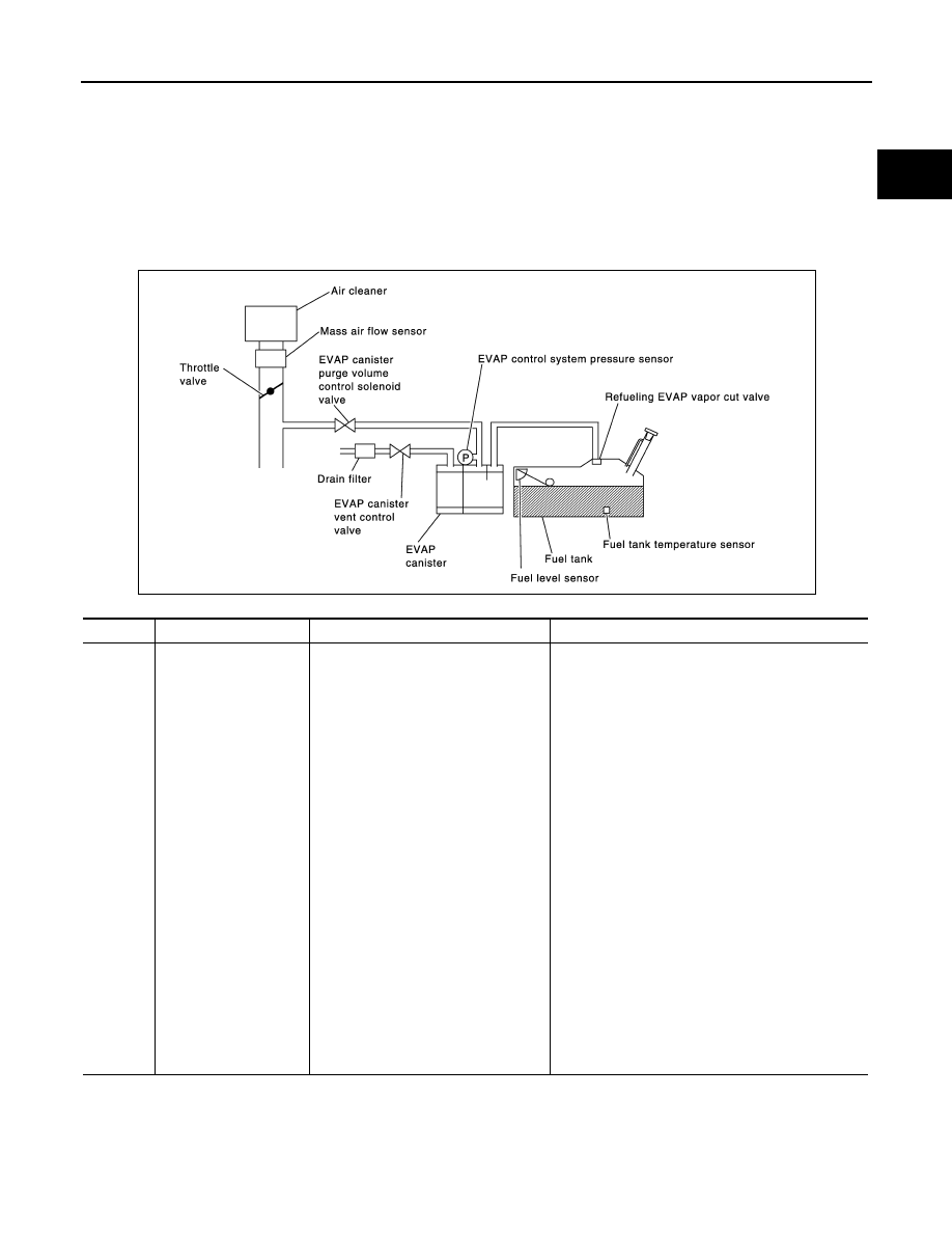
P0456 EVAP CONTROL SYSTEM
On Board Diagnosis Logic
INFOID:0000000009886741
This diagnosis detects very small leaks in the EVAP line between fuel tank and EVAP canister purge volume
control solenoid valve, using the intake manifold vacuum in the same way as conventional EVAP small leak
diagnosis.
If ECM judges a leak which corresponds to a very small leak, the very small leak P0456 will be detected.
If ECM judges a leak equivalent to a small leak, EVAP small leak P0442 will be detected.
If ECM judges there are no leaks, the diagnosis will be OK.
CAUTION:
• Use only a genuine NISSAN fuel filler cap as a replacement. If an incorrect fuel filler cap is used, the
MIL may come on.
• If the fuel filler cap is not tightened properly, the MIL may come on.
• Use only a genuine NISSAN rubber tube as a replacement.
DTC No.
Trouble diagnosis name
DTC detecting condition
Possible cause
P0456
0456
Evaporative emission
control system very
small leak (negative
pressure check)
• EVAP system has a very small leak.
• EVAP system does not operate prop-
erly.
• Incorrect fuel tank vacuum relief valve
• Incorrect fuel filler cap used
• Fuel filler cap remains open or fails to close.
• Foreign matter caught in fuel filler cap.
• Leak is in line between intake manifold and EVAP
canister purge volume control solenoid valve.
• Foreign matter caught in EVAP canister vent con-
trol valve.
• EVAP canister or fuel tank leaks
• EVAP purge line (pipe and rubber tube) leaks
• EVAP purge line rubber tube bent
• Loose or disconnected rubber tube
• EVAP canister vent control valve and the circuit
• EVAP canister purge volume control solenoid
valve and the circuit
• Fuel tank temperature sensor
• Drain filter
• O-ring of EVAP canister vent control valve is miss-
ing or damaged
• EVAP canister is saturated with water
• EVAP control system pressure sensor
• Refueling EVAP vapor cut valve
• ORVR system leaks
• Fuel level sensor and the circuit
• Foreign matter caught in EVAP canister purge vol-
ume control solenoid valve
PBIB3640E