Nissan Titan. Manual - part 231


  Index      Nissan     Nissan Titan (2014 year) - Service and Repair Manual


Search            


Content   ..  229  230  231  232   ..


Nissan Titan. Manual - part 231


P0137, P0157 HO2S2

EC-225

< DTC/CIRCUIT DIAGNOSIS >

[VK56DE]

C

D

E

F

G

H

I

J

K

L

M

A

EC

N

P

O

7. Check “HO2S2 (B1)/(B2)” at idle speed when adjusting “FUEL INJECTION” to 

±25%.

“HO2S2 (B1)/(B2)” should be above 0.58V at least once when the “FUEL INJECTION” is +25%.

“HO2S2 (B1)/(B2)” should be below 0.18V at least once when the “FUEL INJECTION” is 

25%.

CAUTION:

• Discard any heated oxygen sensor which has been dropped from a height of more than 0.5 m (19.7

in) onto a hard surface such as a concrete floor; use a new one.

• Before installing new oxygen sensor, clean exhaust system threads using Oxygen Sensor Thread

Cleaner tool J-43897-18 or J-43897-12 and approved anti-seize lubricant.

 Without CONSULT

1. Start engine and warm it up to the normal operating temperature.
2. Turn ignition switch OFF and wait at least 10 seconds.
3. Start engine and keep the engine speed between 3,500 and 4,000 rpm for at least 1 minute under no load.
4. Let engine idle for 1 minute.
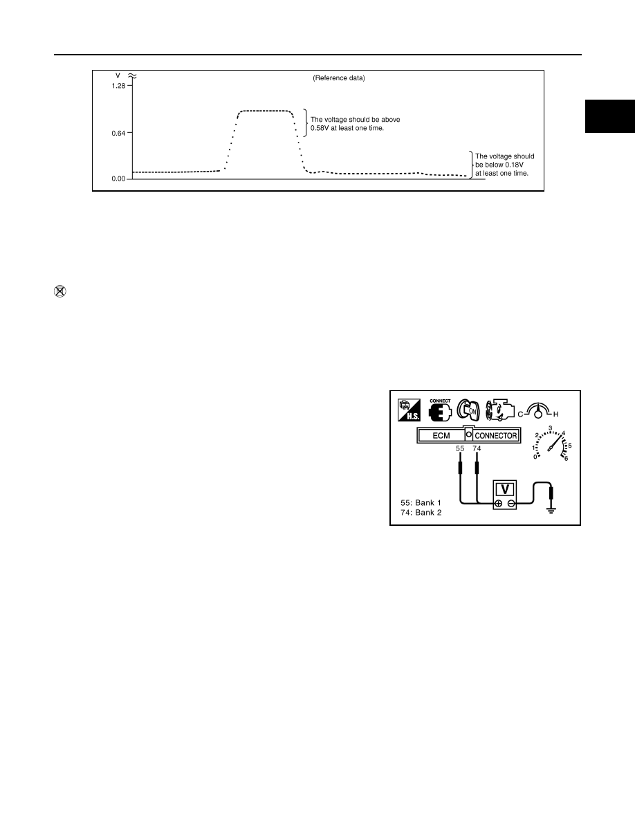
5. Set voltmeter probes between ECM terminal 55 [HO2S2 (B1) signal] or 74 [HO2S2 (B2) signal] and

ground.

6. Check the voltage when revving up to 4,000 rpm under no load

at least 10 times.

(Depress and release accelerator pedal as soon as possible.)

The voltage should be above 0.58V at least once during this

procedure.

If the voltage is above 0.58V at step 6, step 7 is not neces-

sary.

7. Keep vehicle at idling for 10 minutes, then check voltage. Or

check the voltage when coasting from 80 km/h (50 MPH) in D

position.

The voltage should be below 0.18V at least once during this

procedure.

8. If NG, replace heated oxygen sensor 2.

CAUTION:

• Discard any heated oxygen sensor which has been dropped from a height of more than 0.5 m (19.7

in) onto a hard surface such as a concrete floor; use a new one.

• Before installing new oxygen sensor, clean exhaust system threads using Oxygen Sensor Thread

Cleaner tool J-43897-18 or J-43897-12 and approved anti-seize lubricant.

JMBIA0605GB

PBIB2054E

EC-226

< DTC/CIRCUIT DIAGNOSIS >

[VK56DE]

P0138, P0158 HO2S2

P0138, P0158 HO2S2

Component Description

INFOID:0000000009886637

The heated oxygen sensor 2, after three way catalyst (manifold),

monitors the oxygen level in the exhaust gas on each bank.

Even if switching characteristics of the air fuel ratio (A/F) sensor 1

are shifted, the air-fuel ratio is controlled to stoichiometric, by the sig-

nal from the heated oxygen sensor 2.

This sensor is made of ceramic zirconia. The zirconia generates volt-

age from approximately 1V in richer conditions to 0V in leaner condi-

tions.

Under normal conditions the heated oxygen sensor 2 is not used for

engine control operation.

On Board Diagnosis Logic

INFOID:0000000009886638

The heated oxygen sensor 2 has a much longer switching time between rich and lean than the air fuel ratio (A/

F) sensor 1. The oxygen storage capacity of the three way catalyst (manifold) causes the longer switching

time.

MALFUNCTION A

To judge the malfunctions of heated oxygen sensor 2, ECM monitors

whether the voltage is unusually high during the various driving con-

dition such as fuel-cut.

MALFUNCTION B

To judge the malfunctions of heated oxygen sensor 2, ECM monitors

whether the minimum voltage of sensor is sufficiently low during the

various driving condition such as fuel-cut.

DTC Confirmation Procedure

INFOID:0000000009886639

Perform PROCEDURE FOR MALFUNCTION A first.

SEF327R

PBIB1848E

PBIB2376E

DTC No.

Trouble diagnosis name

DTC detecting condition

Possible cause

P0138
0138
(Bank 1)

Heated oxygen sensor 2 
circuit high voltage

A)

An excessively high voltage from the sen-
sor is sent to ECM.

• Harness or connectors

(The sensor circuit is open or shorted)

• Heated oxygen sensor 2

P0158
0158
(Bank 2)

B)

The minimum voltage from the sensor is 
not reached to the specified voltage.

• Harness or connectors

(The sensor circuit is open or shorted)

• Heated oxygen sensor 2
• Fuel pressure
• Fuel injector

P0138, P0158 HO2S2

EC-227

< DTC/CIRCUIT DIAGNOSIS >

[VK56DE]

C

D

E

F

G

H

I

J

K

L

M

A

EC

N

P

O

If DTC cannot be confirmed, perform PROCEDURE FOR MALFUNCTION B.

NOTE:

If DTC Confirmation Procedure has been previously conducted, always perform the following before conduct-

ing the next step. 
1. Turn ignition swich OFF and wait at least 10 seconds.
2. Turn ignition swich ON.
3. Turn ignition swich OFF and wait at least 10 seconds.

PROCEDURE FOR MALFUNCTION A

1. Turn ignition switch ON and select “DATA MONITOR” mode with CONSULT.
2. Start engine and warm it up to the normal operating temperature.
3. Turn ignition switch OFF and wait at least 10 seconds.
4. Start engine and keep the engine speed between 3,500 and 4,000 rpm for at least 1 minute under no load.
5. Let engine idle for 2 minutes.
6. Check 1st trip DTC.
7. If 1st trip DTC is detected, go to 

EC-228, "Diagnosis Procedure"

.

PROCEDURE FOR MALFUNCTION B

 With CONSULT

TESTING CONDITION:

For better results, perform “DTC WORK SUPPORT” at a temperature of 0 to 30 

°C (32 to 86 °F).

1. Turn ignition switch ON and select “DATA MONITOR” mode with CONSULT.
2. Start engine and warm it up to the normal operating temperature.
3. Turn ignition switch OFF and wait at least 10 seconds.
4. Start engine and keep the engine speed between 3,500 and 4,000 rpm for at least 1 minute under no load.
5. Let engine idle for 1 minute.
6. Make sure that “COOLAN TEMP/S” indicates more than 70

°C (158°F).

If not, warm up engine and go to next step when “COOLAN TEMP/S” indication reaches to 70

°C (158°F).

7. Open engine hood.
8. Select “HO2S2 (B1) P1146” (for DTC P0138) or “HO2S2 (B2) P1166” (for DTC P0158) of “HO2S2” in

“DTC WORK SUPPORT” mode with CONSULT.

9. Start engine and following the instruction of CONSULT.

NOTE:

It will take at most 10 minutes until “COMPLETED” is displayed.

10. Make sure that “OK” is displayed after touching “SELF-DIAG RESULTS”.

If “NG” is displayed, refer to 

EC-228, "Diagnosis Procedure"

.

If “CAN NOT BE DIAGNOSED” is displayed, perform the following.

a. Turn ignition switch OFF and leave the vehicle in a cool place (soak the vehicle).
b. Return to step 1.

Overall Function Check

INFOID:0000000009886640

PROCEDURE FOR MALFUNCTION B

Use this procedure to check the overall function of the heated oxygen sensor 2 circuit. During this check, a 1st

trip DTC might not be confirmed.

 With GST

1. Start engine and warm it up to the normal operating temperature.
2. Turn ignition switch OFF and wait at least 10 seconds.
3. Start engine and keep the engine speed between 3,500 and 4,000 rpm for at least 1 minute under no load.
4. Let engine idle for 1 minute.
5. Set voltmeter probes between ECM terminal 55 [HO2S2 (B2) signal] or 74 [HO2S2 (B1) signal] and

ground.

EC-228

< DTC/CIRCUIT DIAGNOSIS >

[VK56DE]

P0138, P0158 HO2S2

6. Check the voltage when revving up to 4,000 rpm under no load

at least 10 times.

(Depress and release accelerator pedal as soon as possible.)

The voltage should be below 0.18V at least once during this

procedure.

If the voltage can be confirmed in step 6, step 7 is not nec-

essary.

7. Keep vehicle at idling for 10 minutes, then check the voltage. Or

check the voltage when coasting from 80 km/h (50 MPH) in D

position.

The voltage should be below 0.18V at least once during this

procedure.

8. If NG, go to 

EC-228, "Diagnosis Procedure"

.

Diagnosis Procedure

INFOID:0000000009886641

PROCEDURE FOR MALFUNCTION A

1.

CHECK GROUND CONNECTIONS

1. Turn ignition switch OFF.

2. Loosen and retighten two ground screws on the body.

Refer to 

EC-154, "Ground Inspection"

.

OK or NG

OK

>> GO TO 2.

NG

>> Repair or replace ground connections.

2.

CHECK HO2S2 GROUND CIRCUIT FOR OPEN AND SHORT

1. Disconnect heated oxygen sensor 2 harness connector.

2. Disconnect ECM harness connector.

3. Check harness continuity between ECM terminal 78 and HO2S2 terminal 4.

Refer to Wiring Diagram.

4. Also check harness for short to ground and short to power.
OK or NG

OK

>> GO TO 3.

NG

>> Repair open circuit or short to ground or short to power in harness or connectors.

3.

CHECK HO2S2 INPUT SIGNAL CIRCUIT FOR OPEN AND SHORT

PBIB2054E

BBIA0354E

Continuity should exist.

BBIA0435E


Content   ..  229  230  231  232   ..