Nissan Titan. Manual - part 229


  Index      Nissan     Nissan Titan (2014 year) - Service and Repair Manual


Search            


Content   ..  227  228  229  230   ..


Nissan Titan. Manual - part 229


P0133, P0153 A/F SENSOR 1

EC-217

< DTC/CIRCUIT DIAGNOSIS >

[VK56DE]

C

D

E

F

G

H

I

J

K

L

M

A

EC

N

P

O

Refer to 

EC-154, "Ground Inspection"

.

OK or NG

OK

>> GO TO 2.

NG

>> Repair or replace ground connections.

2.

RETIGHTEN A/F SENSOR 1

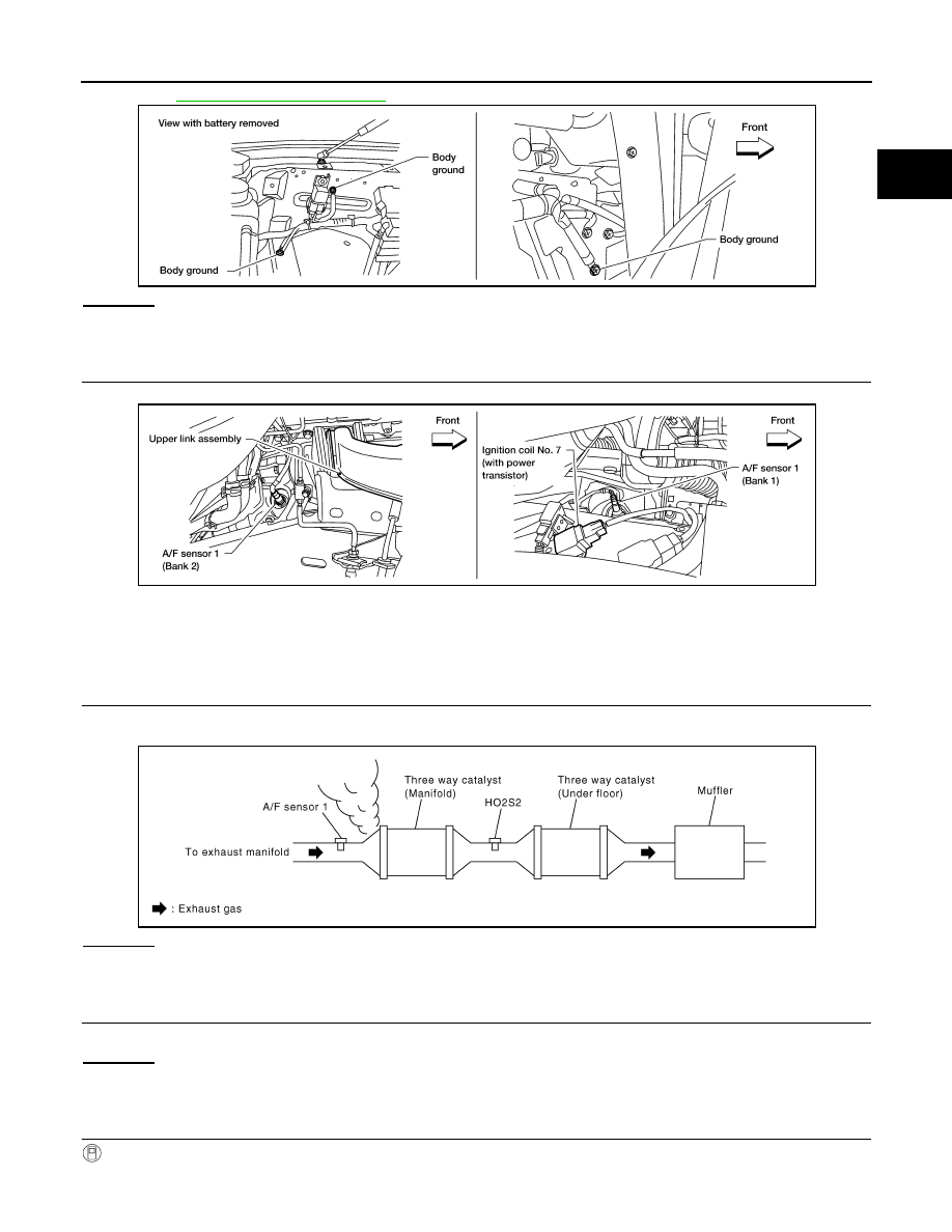
Loosen and retighten the A/F sensor 1.

>> GO TO 3.

3.

CHECK EXHAUST GAS LEAK

1. Start engine and run it at idle.

2. Listen for an exhaust gas leak before three way catalyst (manifold).

OK or NG

OK

>> GO TO 4.

NG

>> Repair or replace.

4.

CHECK FOR INTAKE AIR LEAK

Listen for an intake air leak after the mass air flow sensor.
OK or NG

OK

>> GO TO 5.

NG

>> Repair or replace.

5.

CLEAR THE SELF-LEARNING DATA

 With CONSULT

1. Start engine and warm it up to normal operating temperature.

BBIA0354E

Tightening torque: 50 N-m (5.1 kg-m, 37 ft-lb)

BBIA0375E

PBIB1216E

EC-218

< DTC/CIRCUIT DIAGNOSIS >

[VK56DE]

P0133, P0153 A/F SENSOR 1

2. Select “SELF-LEARNING CONT” in “WORK SUPPORT” mode with CONSULT.

3. Clear the self-learning control coefficient by touching “CLEAR” or “START”.

4. Run engine for at least 10 minutes at idle speed.

Is the 1st trip DTC P0171, P172, P0174 or P0175 detected? Is it difficult to start engine?

 Without CONSULT

1. Start engine and warm it up to normal operating temperature.

2. Turn ignition switch OFF.

3. Disconnect mass air flow sensor harness connector.

4. Restart engine and let it idle for at least 5 seconds.

5. Stop engine and reconnect mass air flow sensor harness con-

nector.

6. Make sure DTC P0102 is displayed.

7. Erase the DTC memory. Refer to 

EC-46, "DIAGNOSIS

DESCRIPTION : Malfunction Indicator Lamp (MIL)"

.

8. Make sure DTC P0000 is displayed.

9. Run engine for at least 10 minutes at idle speed.

Is the 1st trip DTC P0171, P0172, P0174 or P0175 detected?

Is it difficult to start engine?

Yes or No

Yes

>> Perform trouble diagnosis for DTC P0171, P0174 or P0172, P0175. Refer to 

EC-240

 or 

EC-245

.

No

>> GO TO 6.

6.

CHECK A/F SENSOR 1 POWER SUPPLY CIRCUIT

1. Turn ignition switch OFF.

2. Disconnect A/F sensor 1 harness connector.

3. Turn ignition switch ON.

4. Check voltage between A/F sensor 1 terminal 4 and ground with

CONSULT or tester.

OK or NG

OK

>> GO TO 8.

NG

>> GO TO 7.

7.

DETECT MALFUNCTIONING PART

Check the following.

• Harness connectors E5, F14

• IPDM E/R harness connector E119

• 15A fuse

• Harness for open or short between A/F sensor 1 and fuse

>> Repair or replace harness or connectors.

8.

CHECK A/F SENSOR 1 INPUT SIGNAL CIRCUIT FOR OPEN AND SHORT

BBIA0368E

Voltage: Battery voltage

BBIA0376E

JSBIA3095GB

P0133, P0153 A/F SENSOR 1

EC-219

< DTC/CIRCUIT DIAGNOSIS >

[VK56DE]

C

D

E

F

G

H

I

J

K

L

M

A

EC

N

P

O

1. Turn ignition switch OFF.

2. Disconnect ECM harness connector.

3. Check harness continuity between A/F sensor 1 terminal and ECM terminal as follows.

Refer to Wiring Diagram.

4. Check harness continuity between the following terminals and ground.

Refer to Wiring Diagram.

5. Also check harness for short to power.
OK or NG

OK

>> GO TO 9.

NG

>> Repair open circuit or short to ground or short to power in harness or connectors.

9.

CHECK AIR FUEL RATIO (A/F) SENSOR 1 HEATER

Refer to 

EC-165, "Component Inspection"

.

OK or NG

OK

>> GO TO 10.

NG

>> GO TO 13.

10.

CHECK MASS AIR FLOW SENSOR

Refer to 

EC-178, "Component Inspection"

.

OK or NG

OK

>> GO TO 11. 

NG

>> Replace mass air flow sensor.

11.

CHECK PCV VALVE

Refer to 

EC-479, "Component Inspection"

.

OK or NG

OK

>> GO TO 12.

NG

>> Repair or replace PCV valve.

12.

CHECK INTERMITTENT INCIDENT

Perfor

GI-39, "How to Check Terminal"

 and 

GI-42, "Intermittent Incident"

.

OK or NG

OK

>> GO TO 13.

NG

>> Repair or replace.

13.

REPLACE AIR FUEL RATIO (A/F) SENSOR 1

Replace malfunctioning air fuel ratio (A/F) sensor 1.

CAUTION:

A/F sensor 1 terminal

ECM terminal

Bank1

1

35

2

56

Bank 2

1

16

2

75

Continuity should exist.

Bank 1

Bank 2

A/F sensor 1 terminal

ECM terminal

A/F sensor 1 terminal

ECM terminal

1

35

1

16

2

56

2

75

Continuity should not exist.

EC-220

< DTC/CIRCUIT DIAGNOSIS >

[VK56DE]

P0133, P0153 A/F SENSOR 1

• Discard any air fuel ratio (A/F) sensor which has been dropped from a height of more than 0.5 m

(19.7 in) onto a hard surface such as a concrete floor; use a new one.

• Before installing new air fuel ratio (A/F) sensor, clean exhaust system threads (using Oxygen Sensor

Thread Cleaner tool J-43897-18 or J-43897-12) and approved anti-seize lubricant.

>> INSPECTION END


Content   ..  227  228  229  230   ..