Nissan Titan. Manual - part 219


  Index      Nissan     Nissan Titan (2014 year) - Service and Repair Manual


Search            


Content   ..  217  218  219  220   ..


Nissan Titan. Manual - part 219


P0102, P0103 MAF SENSOR

EC-177

< DTC/CIRCUIT DIAGNOSIS >

[VK56DE]

C

D

E

F

G

H

I

J

K

L

M

A

EC

N

P

O

Diagnosis Procedure

INFOID:0000000009886574

1.

INSPECTION START

Which malfunction (P0102 or P0103) is duplicated?
P0102 or P0103

P0102 >> GO TO 2.

P0103 >> GO TO 3.

2.

CHECK INTAKE SYSTEM

Check the following for connection.

• Air duct

• Vacuum hoses

• Intake air passage between air duct to intake manifold
OK or NG

OK

>> GO TO 3.

NG

>> Reconnect the parts.
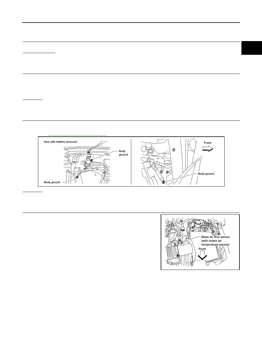
3.

RETIGHTEN GROUND SCREWS

1. Turn ignition switch OFF.

2. Loosen and retighten three ground screws on the body.

Refer to 

EC-154, "Ground Inspection"

.

OK or NG

OK

>> GO TO 4.

NG

>> Repair or replace ground connections.

4.

CHECK MAF SENSOR POWER SUPPLY CIRCUIT

1. Disconnect mass air flow (MAF) sensor harness connector.

2. Turn ignition switch ON.

BBIA0354E

BBIA0368E

EC-178

< DTC/CIRCUIT DIAGNOSIS >

[VK56DE]

P0102, P0103 MAF SENSOR

3. Check voltage between MAF sensor terminal 2 and ground with

CONSULT or tester. 

OK or NG

OK

>> GO TO 6.

NG

>> GO TO 5.

5.

DETECT MALFUNCTIONING PART

Check the following.

• Harness connectors E2, F32

• Harness for open or short between IPDM E/R and mass air flow sensor

• Harness for open or short between mass air flow sensor and ECM

>> Repair harness or connectors.

6.

CHECK MAF SENSOR GROUND CIRCUIT FOR OPEN AND SHORT

1. Turn ignition switch OFF.

2. Disconnect ECM harness connector.

3. Check harness continuity between MAF sensor terminal 3 and ECM terminal 67.

Refer to Wiring Diagram.

4. Also check harness for short to ground and short to power.
OK or NG

OK

>> GO TO 7.

NG

>> Repair open circuit or short to ground or short to power in harness or connectors.

7.

CHECK MAF SENSOR INPUT SIGNAL CIRCUIT FOR OPEN AND SHORT

1. Check harness continuity between MAF sensor terminal 4 and ECM terminal 51.

Refer to Wiring Diagram. 

2. Also check harness for short to ground and short to power.
OK or NG

OK

>> GO TO 8. 

NG

>> Repair open circuit or short to ground or short to power in harness or connectors.

8.

CHECK MASS AIR FLOW SENSOR

Refer to 

EC-178, "Component Inspection"

.

OK or NG

OK

>> GO TO 9.

NG

>> Replace mass air flow sensor.

9.

CHECK INTERMITTENT INCIDENT

Refer to 

GI-39, "How to Check Terminal"

 and 

GI-42, "Intermittent Incident"

.

>> INSPECTION END

Component Inspection

INFOID:0000000009886575

MASS AIR FLOW SENSOR

Voltage: Battery voltage

PBIB1168E

Continuity should exist.

Continuity should exist.

P0102, P0103 MAF SENSOR

EC-179

< DTC/CIRCUIT DIAGNOSIS >

[VK56DE]

C

D

E

F

G

H

I

J

K

L

M

A

EC

N

P

O

 With CONSULT

1. Reconnect all harness connectors disconnected.
2. Start engine and warm it up to normal operating temperature.
3. Connect CONSULT and select “DATA MONITOR” mode.
4. Select “MAS A/F SE-B1” and check indication under the following conditions.

*: Check for linear voltage rise in response to engine being increased to about 4,000 rpm.

5. If the voltage is out of specification, proceed the following.
a. Check for the cause of uneven air flow through mass air flow sensor. Refer to following.

• Crushed air ducts

• Malfunctioning seal of air cleaner element

• Uneven dirt of air cleaner element

• Improper specification of intake air system parts

b. If NG, repair or replace malfunctioning part and perform step 2 to 4 again.

If OK, go to next step.

6. Turn ignition switch OFF.
7. Disconnect mass air flow sensor harness connector and reconnect it again.
8. Perform step 2 to 4 again.
9. If NG, clean or replace mass air flow sensor.

 Without CONSULT

1. Reconnect all harness connectors disconnected.
2. Start engine and warm it up to normal operating temperature.
3. Check voltage between ECM terminal 51 (Mass air flow sensor

signal) and ground.

*: Check for linear voltage rise in response to engine being increased to about 4,000 rpm.

4. If the voltage is out of specification, proceed the following.
a. Check for the cause of uneven air flow through mass air flow sensor. Refer to following.

• Crushed air ducts

• Malfunctioning seal of air cleaner element

• Uneven dirt of air cleaner element

• Improper specification of intake air system parts

b. If NG, repair or replace malfunctioning part and perform step 2 and 3 again.

If OK, go to next step.

5. Turn ignition switch OFF.
6. Disconnect mass air flow sensor harness connector and reconnect it again.
7. Perform step 2 and 3 again.

Condition

MAS A/F SE-B1 (V)

Ignition switch ON (Engine stopped.)

Approx. 0.4

Idle (Engine is warmed-up to normal 
operating temperature.)

0.9 - 1.3

2,500 rpm (Engine is warmed-up to 
normal operating temperature.)

1.7 - 2.1

Idle to about 4,000 rpm

0.9 - 1.3 to Approx. 2.4*

Condition

MAS A/F SE-B1 (V)

Ignition switch ON (Engine stopped.)

Approx. 0.4

Idle (Engine is warmed-up to normal 
operating temperature.)

0.9 - 1.3

2,500 rpm (Engine is warmed-up to 
normal operating temperature.)

1.7 - 2.1

Idle to about 4,000 rpm

0.9 - 1.3 to Approx. 2.4*

PBIB1106E

EC-180

< DTC/CIRCUIT DIAGNOSIS >

[VK56DE]

P0102, P0103 MAF SENSOR

8. If NG, clean or replace mass air flow sensor.


Content   ..  217  218  219  220   ..