Nissan Titan. Manual - part 161
DLN-216
< DTC/CIRCUIT DIAGNOSIS >
[REAR FINAL DRIVE: M226 (ELD) ]
U1000 CAN COMM CIRCUIT
DTC/CIRCUIT DIAGNOSIS
U1000 CAN COMM CIRCUIT
Description
INFOID:0000000009886105
CAN (Controller Area Network) is a serial communication line for real time application. It is an on-vehicle mul-
tiplex communication line with high data communication speed and excellent error detection ability. Many elec-
tronic control units are equipped onto a vehicle and each control unit shares information and links with other
control units during operation (not independent). In CAN communication, control units are connected with 2
communication lines (CAN-H, CAN-L) allowing a high rate of information transmission with less wiring. Each
control unit transmits/receives data but selectively reads required data only.
CAN Communication Signal Chart. Refer to
LAN-46, "CAN Communication Signal Chart"
DTC Logic
INFOID:0000000009886106
DTC DETECTION LOGIC
Diagnosis Procedure
INFOID:0000000009886107
1.
PERFORM SELF DIAGNOSTIC
1. Turn ignition switch ON and wait for 2 seconds or more.
2. Check “Self Diagnostic Result” of differential lock control unit.
Is “CAN COMM CIRCUIT” displayed?
YES
>> Refer to
DLN-214, "CONSULT Function (DIFF LOCK)"
.
NO
>> Refer to
GI-42, "Intermittent Incident"
.
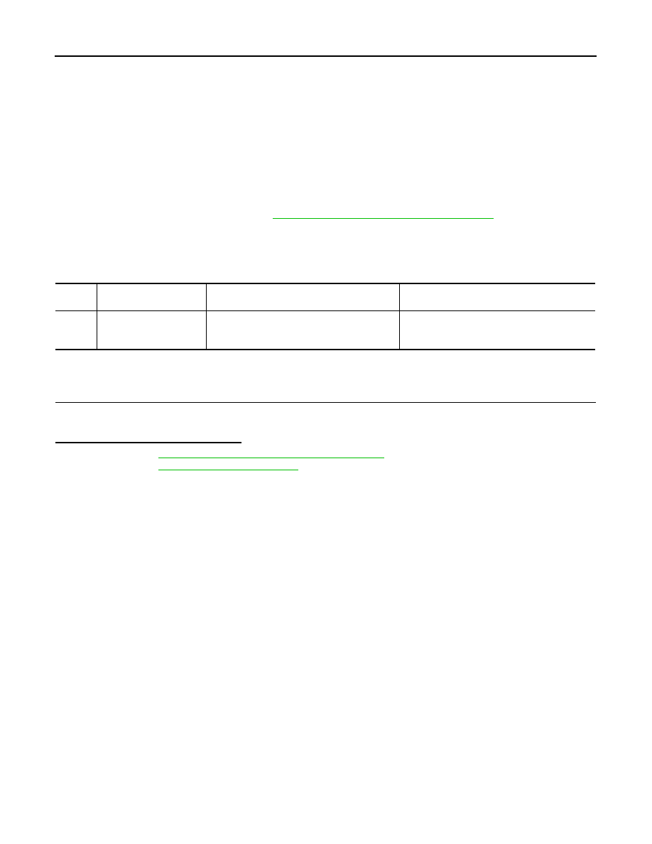
DTC
Display contents of CON-
SULT
Diagnostic item is detected when ...
Probable malfunction location
U1000
CAN COMM CIRCUIT
When differential lock control unit is not trans-
mitting or receiving CAN communication signal
for 2 seconds or more.
CAN communication system