Nissan Titan. Manual - part 159
DLN-208
< BASIC INSPECTION >
[REAR FINAL DRIVE: M226 (ELD) ]
DIAGNOSIS AND REPAIR WORKFLOW
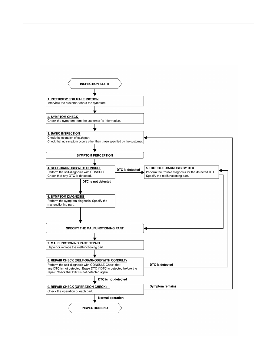
BASIC INSPECTION
DIAGNOSIS AND REPAIR WORKFLOW
Work Flow
INFOID:0000000009886097
OVERALL SEQUENCE
DETAILED FLOW
AWEIA0214GB
|
|
|
DLN-208 < BASIC INSPECTION > [REAR FINAL DRIVE: M226 (ELD) ] DIAGNOSIS AND REPAIR WORKFLOW BASIC INSPECTION DIAGNOSIS AND REPAIR WORKFLOW Work Flow INFOID:0000000009886097 OVERALL SEQUENCE DETAILED FLOW AWEIA0214GB |