Nissan Titan. Manual - part 157


  Index      Nissan     Nissan Titan (2014 year) - Service and Repair Manual


Search            


Content   ..  155  156  157  158   ..


Nissan Titan. Manual - part 157


DLN-200

< UNIT DISASSEMBLY AND ASSEMBLY >

[REAR FINAL DRIVE: M226 ]

REAR FINAL DRIVE ASSEMBLY

CAUTION:

Do not change the side bearing side bearing adjusters by

different amounts as it will change the side bearing preload

torque.

d. Tighten side bearing cap bolts to the specified torque.
e. Install adjuster lock plate and tighten to the specified torque.

CAUTION:

Check tooth contact and total preload torque after adjusting

side bearing adjuster. Refer to 

DLN-206, "Inspection and

Adjustment"

.

Companion Flange Runout

1. Rotate companion flange and check for runout on the compan-

ion flange face (inner side of the bolt holes) and companion

flange inner side (socket diameter) using suitable tool. Refer to

DLN-206, "General Specification"

.

2. If the runout is outside the runout limit, follow the procedure

below to adjust.

a. Rotate the companion flange on the drive pinion by 90

°, 180°

and 270

° while checking for the position where the runout is

minimum.

b. If the runout is still outside of the runout limit after the companion

flange has been rotated on the drive pinion, possible cause

could be an assembly malfunction of drive pinion and drive pin-

ion bearing or a malfunctioning drive pinion bearing.

c.

If the runout is still outside of the runout limit after replacing the companion flange. Replace the rear final

drive assembly. Refer to 

DLN-196, "Removal and Installation"

.

DISASSEMBLY

Differential Assembly

1. Remove carrier cover bolts.
2. Remove carrier cover using Tool.

CAUTION:

• Do not damage the mating surface.

• Do not insert flat-bladed screwdriver, this will damage the

mating surface.

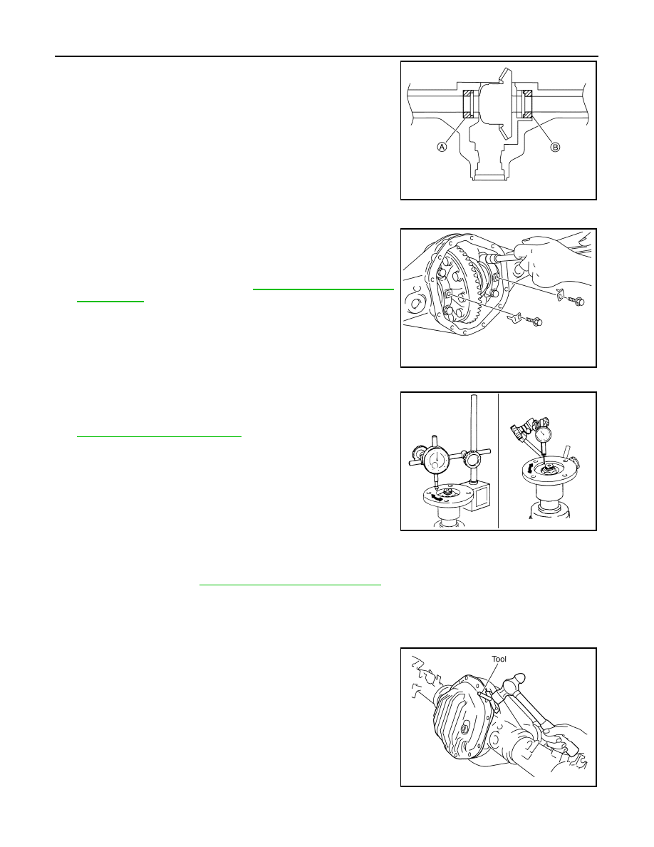
If the backlash is greater than specification:

Loosen side bearing adjuster (A) and tighten side 
bearing adjuster (B) by the same amount.

If the backlash is less than specification:

Loosen side bearing adjuster (B) and tighten side 
bearing adjuster (A) by the same amount.

PDIA0330E

PDIA0331E

SDIA2078E

Tool number

: KV10111100 (J-37228)

PDIA1041E

REAR FINAL DRIVE ASSEMBLY

DLN-201

< UNIT DISASSEMBLY AND ASSEMBLY >

[REAR FINAL DRIVE: M226 ]

C

E

F

G

H

I

J

K

L

M

A

B

DLN

N

O

P

3. For proper reinstallation, paint matching mark on one side of

side bearing cap.

CAUTION:

• Side bearing caps are line-board for initial assembly. The

matching marks are used to reinstall them in their original

positions.

• For matching mark, use paint. Do not damage side bear-

ing cap.

4. Remove adjuster lock plates.
5. Remove side bearing caps.

6. Loosen side bearing adjusters using Tool.

7. Remove the differential case assembly. Label side bearing outer

races to keep them together with inner races. Do not mix them

up.

Drive Pinion Assembly

1. Put matching marks on the companion flange at location (A) and

drive pinion using paint as shown.

CAUTION:

Use paint to make the matching marks. Do not damage the

companion flange or drive pinion.

PDIA0310E

PDIA0331E

Tool number

:  —  (C-4164)

PDIA0337E

PDIA0312E

PDIA0675E

DLN-202

< UNIT DISASSEMBLY AND ASSEMBLY >

[REAR FINAL DRIVE: M226 ]

REAR FINAL DRIVE ASSEMBLY

2. Remove drive pinion lock nut and washer using suitable tool.

3. Remove companion flange using a suitable tool.

4. Remove oil seal/dust shield and discard.

CAUTION:

Do not reuse the differential oil seal.

5. Remove front oil seal using Tool.

CAUTION:

Do not damage gear carrier.

6. Remove drive pinion front bearing thrust washer.
7. Remove drive pinion assembly (with rear inner bearing race and

collapsible spacer) out of gear carrier.

CAUTION:

Do not drop drive pinion assembly.

8. Remove collapsible spacer from drive pinion assembly and discard collapsible spacer.

CAUTION:

Do not reuse the collapsible spacer.

INSPECTION AFTER DISASSEMBLY

Clean the disassembled parts. Then inspect the parts for wear or damage. If wear or damage are found, follow

the measures below.

PDIA0314E

PDIA0315E

Tool number

: ST33290001 (J-34286)

SDIA2586E

PDIA0316E

REAR FINAL DRIVE ASSEMBLY

DLN-203

< UNIT DISASSEMBLY AND ASSEMBLY >

[REAR FINAL DRIVE: M226 ]

C

E

F

G

H

I

J

K

L

M

A

B

DLN

N

O

P

Drive Pinion and Drive Gear

• If the gear teeth do not mesh or line-up correctly, replace with new rear final drive assembly. Refer to 

DLN-

196, "Removal and Installation"

.

• If the gears are worn, cracked, damaged, pitted or chipped (by friction) noticeably, replace with new rear final

drive assembly. Refer to 

DLN-196, "Removal and Installation"

.

Bearings

• If bearings are chipped (by friction), pitted, worn, rusted, scratched, or unusual noise is coming from the

bearing, replace with new rear final drive assembly. Refer to 

DLN-196, "Removal and Installation"

.

Differential Case Assembly

• If the gears are worn, cracked, damaged, pitted or chipped (by friction) noticeably, replace with new rear final

drive assembly. Refer to 

DLN-196, "Removal and Installation"

.

• If the movement is not smooth when pushing cam ring of differential case assembly by hand. Replace with

new rear final drive assembly. Refer to 

DLN-196, "Removal and Installation"

.

Companion Flange

• If any chips (about 0.1mm, 0.004 in) or other damage on the companion flange surface which contacts the

front oil seal lips are found, replace with new one. Refer to 

DLN-196, "Removal and Installation"

.

ASSEMBLY

Drive Pinion Assembly

1. Install drive pinion front bearing thrust washer.
2. Apply multi-purpose grease to new front oil seal lip. Install front

oil seal into gear carrier using Tool.

CAUTION:

• Do not reuse front oil seal.

• Do not incline the new front oil seal when installing.

• Apply multi-purpose grease to the lips of the new front oil

seal.

3. Install new collapsible spacer to drive pinion. And then install

drive pinion assembly into gear carrier.

CAUTION:

• Do not reuse collapsible spacer.

• Do not damage front oil seal.

4. Install a new oil seal/dust shield.
5. Install the companion flange onto the drive pinion while aligning

the matching marks. Then tap the companion flange using suit-

able tool.

CAUTION:

Do not damage companion flange or front oil seal.

Tool number

: ST15310000 ( — )

PDIA0326E

SDIA2595E

PDIA0328E


Content   ..  155  156  157  158   ..