Nissan Titan. Manual - part 156


  Index      Nissan     Nissan Titan (2014 year) - Service and Repair Manual


Search            


Content   ..  154  155  156  157   ..


Nissan Titan. Manual - part 156


DLN-196

< UNIT REMOVAL AND INSTALLATION >

[REAR FINAL DRIVE: M226 ]

REAR FINAL DRIVE

UNIT REMOVAL AND INSTALLATION

REAR FINAL DRIVE

Removal and Installation

INFOID:0000000009886093

REMOVAL

CAUTION:

• Do not damage spline, companion flange and front oil seal when removing propeller shaft.

• Before removing final drive assembly or rear axle assembly, disconnect ABS sensor harness con-

nector from the assembly and move it away from final drive/rear axle assembly area. Failure to do so

may result in sensor wires being damaged and sensor becoming inoperative.

1. Remove the rear wheels and tires using power tool. Refer to 

WT-48, "Balancing Wheels"

.

2. Remove rear brake disc rotors. Refer to 

BR-36, "Removal and Installation of Brake Caliper and Disc

Rotor"

.

3. Remove the rear propeller shaft. Refer to 

DLN-139, "Removal and Installation"

 (2S1410), 

DLN-148,

"Removal and Installation"

 (3S1410).

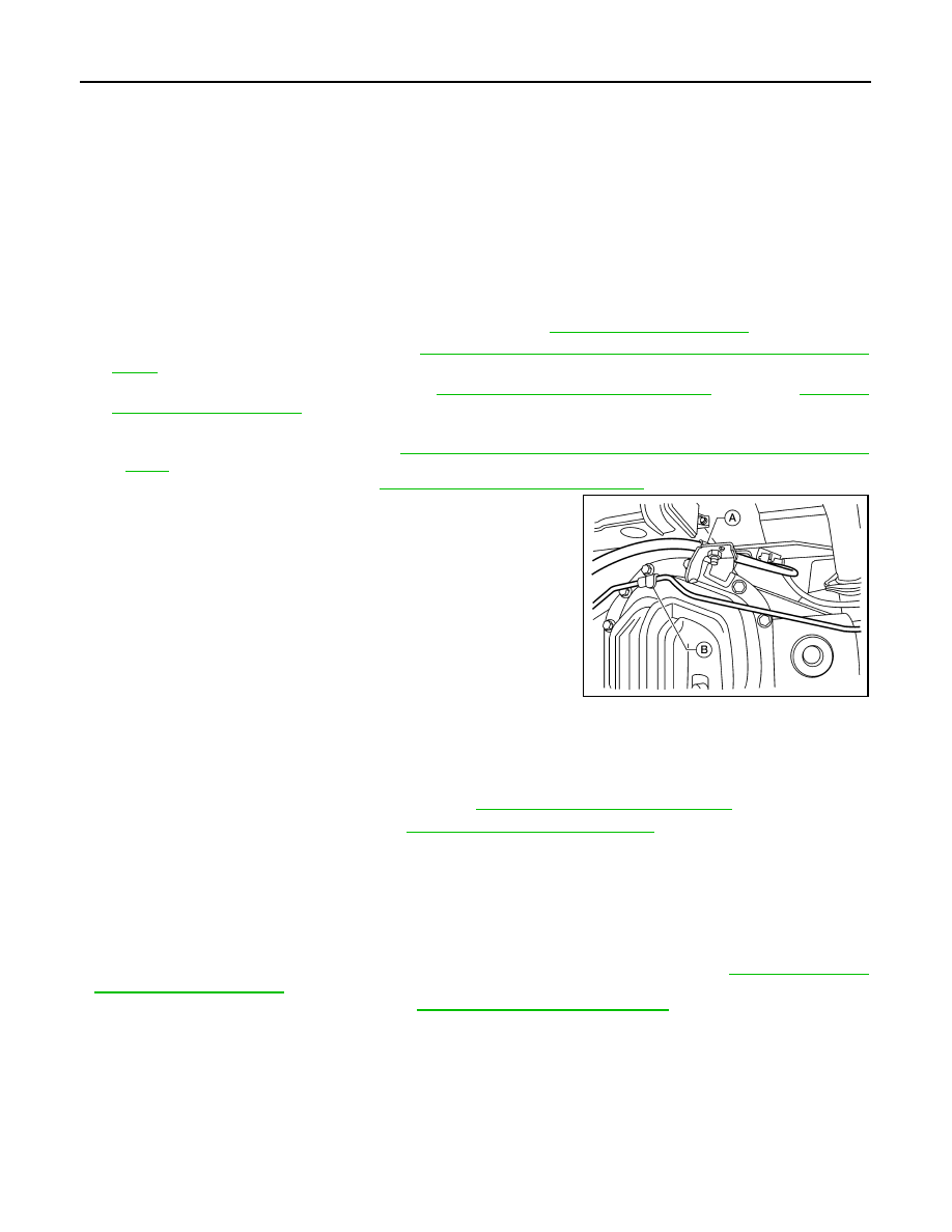
4. Disconnect the following components from the rear final drive assembly.

• Brake tube block connectors. Refer to 

BR-22, "Removal and Installation of Rear Brake Piping and Brake

Hose"

.

• ABS sensor wire harness. Refer to 

BRC-113, "Removal and Installation"

.

• Parking brake cable (A).

• Brake tube (B).

5. Disconnect brake hose from brake tube at the mounting clip on top of rear final drive assembly. Then

remove the metal clip to disconnect brake line from the mounting clip on top of the rear final drive assem-

bly. 

6. Support rear final drive assembly using a suitable jack.
7. Remove rear shock absorber lower bolts. Refer to 

RSU-10, "Removal and Installation"

.

8. Remove leaf spring U-bolt nuts. Refer to 

RSU-7, "Removal and Installation"

.

9. Remove rear final drive assembly.

CAUTION:

Secure rear final drive assembly to the jack while removing it.

INSTALLATION

Installation is in the reverse order of removal.

CAUTION:

• Check the rear final drive assembly differential gear oil after installation. Refer to 

DLN-192, "Chang-

ing Differential Gear Oil"

.

• Bleed the air from brake system. Refer to 

BR-16, "Bleeding Brake System"

.

WDIA0330E

REAR FINAL DRIVE ASSEMBLY

DLN-197

< UNIT DISASSEMBLY AND ASSEMBLY >

[REAR FINAL DRIVE: M226 ]

C

E

F

G

H

I

J

K

L

M

A

B

DLN

N

O

P

UNIT DISASSEMBLY AND ASSEMBLY

REAR FINAL DRIVE ASSEMBLY

Disassembly and Assembly

INFOID:0000000009886094

COMPONENTS

ASSEMBLY INSPECTION AND ADJUSTMENT

1.

Drive pinion lock nut

2.

Drive pinion lock nut washer

3.

Companion flange

4.

Oil seal/dust shield

5.

Front oil seal

6.

Drive pinion front bearing thrust washer 
(non-serviceable)

7.

Gear carrier (non-serviceable)

8.

Collapsible spacer

9.

Drain plug (non-serviceable)

10. Side bearing cap (non-serviceable)

11. Adjuster lock plate (non-serviceable) 12. Carrier cover

13. Filler plug

14. Bracket

15. Drive pinion assembly (non-serviceable)

16. Side bearing outer race

17. Differential case assembly (non-ser-

viceable)

A.

Gear oil

AWDIA0666GB

DLN-198

< UNIT DISASSEMBLY AND ASSEMBLY >

[REAR FINAL DRIVE: M226 ]

REAR FINAL DRIVE ASSEMBLY

• Drain the differential gear oil before inspection and adjustment. Refer to 

DLN-192, "Changing Differential

Gear Oil"

.

• Remove and install the carrier cover as necessary for inspection and adjustment. Refer to 

DLN-195,

"Removal and Installation"

.

Total Preload Torque

1. Rotate the drive pinion back and forth 2 to 3 times to check for unusual noise and rotation malfunction.
2. Rotate the drive pinion at least 20 times to check for smooth operation of the bearings.
3. Measure total preload torque using Tool. Refer to 

DLN-206,

"Inspection and Adjustment"

.

• If the measured value is out of the specification, check and

adjust each part. Adjust the drive pinion bearing preload

torque first, then adjust the side bearing preload torque.

NOTE:

Total preload torque = Drive pinion bearing preload torque +

Side bearing preload torque

Tooth Contact

Checking gear tooth contact pattern is necessary to verify correct relationship between drive gear and drive

pinion. Gears which are not positioned in proper arrangement may be noisy and/or have a short life. Check

gear tooth contact pattern to obtain the best contact for low noise and long life.
1. Thoroughly clean drive gear and drive pinion teeth.
2. Apply red lead to the drive gear.

• Apply red lead to both faces of three to four gears, at four loca-

tions evenly spaced on the drive gear.

3. Hold companion flange steady by hand and rotate drive gear in

both directions.

Tool number

: ST3127S000 (J-25765-A)

If the total preload torque is greater than specification

On drive pinion bearings

: Replace collapsible spacer.

On side bearings

: Loosen side bearing adjuster.

If the total preload torque is less than specification

On drive pinion bearings

: Tighten drive pinion lock nut.

On side bearings

: Tighten side bearing adjuster.

PDIA0309E

PDIA0321E

PDIA0322E

REAR FINAL DRIVE ASSEMBLY

DLN-199

< UNIT DISASSEMBLY AND ASSEMBLY >

[REAR FINAL DRIVE: M226 ]

C

E

F

G

H

I

J

K

L

M

A

B

DLN

N

O

P

4. If outside the standard, replace the final drive assembly. Refer to 

DLN-196, "Removal and Installation"

.

Backlash

1. Fit a dial indicator to the drive gear face to measure the back-

lash.

2. If the backlash is outside of the specification, adjust each side bearing side bearing adjuster.
a. Remove adjuster lock plates.
b. Loosen side bearing cap bolts.

c. Tighten or loosen each side bearing adjuster using Tool.

SDIA2591E

Backlash

Refer to 

DLN-206, "Inspection and Adjust-

ment"

SDIA2640E

PDIA0331E

Tool number

:  —  (C-4164)

PDIA0337E


Content   ..  154  155  156  157   ..