Nissan Titan. Manual - part 134


  Index      Nissan     Nissan Titan (2014 year) - Service and Repair Manual


Search            


Content   ..  132  133  134  135   ..


Nissan Titan. Manual - part 134


DLN-108

< UNIT DISASSEMBLY AND ASSEMBLY >

[TRANSFER: TX15B]

TRANSFER ASSEMBLY

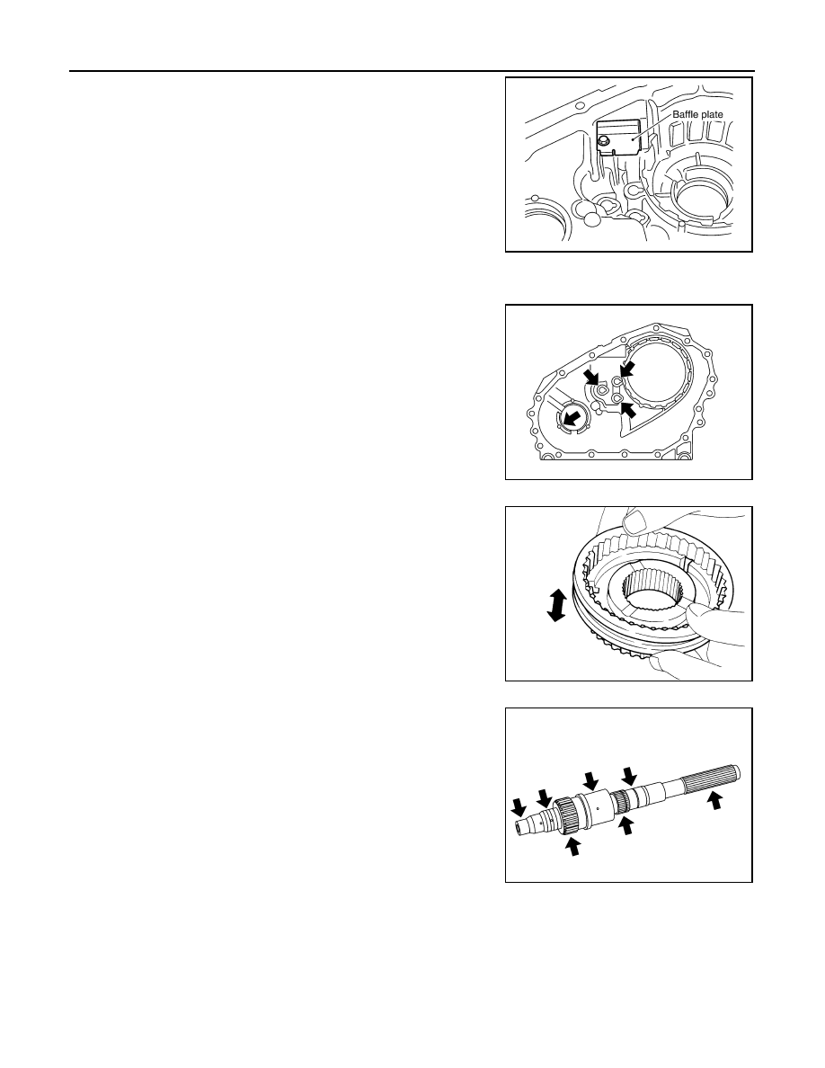
37. Remove the baffle plate from the front case.
38. Remove the breather tube from the front case.

INSPECTION AFTER DISASSEMBLY 

Case

Check the contact surfaces of the shift rod and bearing for wear and

damage. If any is found, replace with a new one.

Sleeve

Check the items below. If necessary, replace them with new ones.

• Damage and excessive wear of the contact surfaces of the

sprocket, mainshaft and sleeve.

• Sleeve must move smoothly.

Gear, Shaft and Drive Chain

Check the items below. If necessary, replace them with new ones.

• Damage, peeling, uneven wear and bending of the shaft.

• Excessive wear, damage and peeling of the gear.

Bearing

PDIA0105E

PDIA0145E

PDIA0136E

SDIA2790E

TRANSFER ASSEMBLY

DLN-109

< UNIT DISASSEMBLY AND ASSEMBLY >

[TRANSFER: TX15B]

C

E

F

G

H

I

J

K

L

M

A

B

DLN

N

O

P

Check the bearing for damage and rough rotation. If necessary,

replace it with a new one.

ASSEMBLY

1. Install the breather tube.

CAUTION:

Install breather tube in the direction shown.

2. Install the baffle plate to the front case. Tighten the bolt to the

specified torque. Refer to 

DLN-101, "Disassembly and Assem-

bly"

.

CAUTION:

Install baffle plate by pushing it in the direction shown

while tightening the bolt.

3. Install the input bearing to the front case using Tool.

4. Install the new snap ring to the front case.

CAUTION:

Do not reuse snap ring.

MTF0041D

PDIA0107E

SDIA2479E

Tool number

: ST30720000 (J-25405)

PDIA0108E

PDIA0103E

DLN-110

< UNIT DISASSEMBLY AND ASSEMBLY >

[TRANSFER: TX15B]

TRANSFER ASSEMBLY

5. Install the internal gear with the groove facing up into the front

case.

6. Install the new snap ring to the front case.

CAUTION:

Do not reuse snap ring.

7. Install the planetary carrier assembly and sun gear assembly to

the front case using Tool.

8. Install the new snap ring to the sun gear.

CAUTION:

• Do not reuse snap ring.

• Do not damage sun gear.

9. Set the L-H sleeve together with the L-H shift fork assembly onto

the planetary carrier assembly.

PDIA0102E

PDIA0101E

Tool number

: KV38100200 ( — )

SDIA2791E

PDIA0099E

SDIA2438E

TRANSFER ASSEMBLY

DLN-111

< UNIT DISASSEMBLY AND ASSEMBLY >

[TRANSFER: TX15B]

C

E

F

G

H

I

J

K

L

M

A

B

DLN

N

O

P

10. Install the control shift rod assembly to the front case.

CAUTION:

Set pin of L-H shift fork assembly into the groove of drum

cam.

11. Turn the control shift rod assembly fully counterclockwise.

12. Install the L-H shift rod assembly through the L-H shift fork

assembly opening to the front case.

CAUTION:

Set pin of L-H shift rod assembly into the groove of drum

cam.

13. Install the mainshaft to the sun gear assembly.

14. Install the drive chain to the front drive shaft and sprocket.

CAUTION:

Install with the Identification mark of drive chain on the side

of the rear bearing of front drive shaft.

15. Install the drive chain together with the front drive shaft and

sprocket to the front case.

16. Install the 2-4 sleeve and 2-4 shift fork assembly to the main-

shaft.

CAUTION:

• Install with proper orientation of 2-4 sleeve.

• Install 2-4 shift fork with engaging the grooves of 2-4 shift

fork in the retaining pin of 2-4 shift bracket.

WDIA0215E

WDIA0216E

PDIA0110E

SDIA2464E

SDIA2467E


Content   ..  132  133  134  135   ..