Nissan Titan. Manual - part 128


  Index      Nissan     Nissan Titan (2014 year) - Service and Repair Manual


Search            


Content   ..  126  127  128  129   ..


Nissan Titan. Manual - part 128


DLN-84

< PRECAUTION >

[TRANSFER: TX15B]

PRECAUTIONS

Pattern A

1. Stop vehicle and move A/T shift selector to N position with brake pedal depressed. Stay in N for at least 2

seconds.

2. Turn 4WD shift switch to 4LO position. Stay in 4LO for at least 2 seconds.
3. Turn ignition switch OFF.
4. Start engine.
5. Erase self-diagnosis. Refer to 

DLN-16, "CONSULT Function (ALL MODE AWD/4WD)"

.

6. Check 4WD shift indicator lamp and 4LO indicator lamp again. Refer to CHECK 4WD SHIFT INDICATOR

PATTERN.

If 4WD shift indicator lamp and 4LO indicator lamp do not indicate proper pattern, install new transfer con-

trol unit and retry the above check.

Pattern B

1. Stop vehicle and move A/T shift selector to N position with brake pedal depressed. Stay in N for at least 2

seconds.

2. Turn ignition switch OFF.
3. Start engine.
4. Erase self-diagnosis. Refer to 

DLN-16, "CONSULT Function (ALL MODE AWD/4WD)"

.

5. Check 4WD shift indicator lamp and 4LO indicator lamp again. Refer to CHECK 4WD SHIFT INDICATOR

PATTERN.

If 4WD shift indicator lamp and 4LO indicator lamp do not indicate proper pattern, install new transfer con-

trol unit and retry the above check.

METHOD FOR ADJUSTMENT WITH 4WD SHIFT SWITCH AT 4H OR 4LO

1. Start engine. Run the engine for at least 10 seconds.
2. Stop vehicle and move A/T shift selector to N position with brake pedal depressed. Stay in N for at least 2

seconds.)

3. Turn 4WD shift switch to 2WD position. Stay in 2WD for at least 2 seconds.
4. Turn ignition switch OFF.
5. Start engine.
6. Erase self-diagnosis. Refer to 

DLN-16, "CONSULT Function (ALL MODE AWD/4WD)"

.

7. Check 4WD shift indicator lamp and 4LO indicator lamp again. Refer to CHECK 4WD SHIFT INDICATOR

PATTERN.

If 4WD shift indicator lamp and 4LO indicator lamp do not indicate proper pattern, install new transfer con-

trol unit and retry the above check.

Precaution

INFOID:0000000009886027

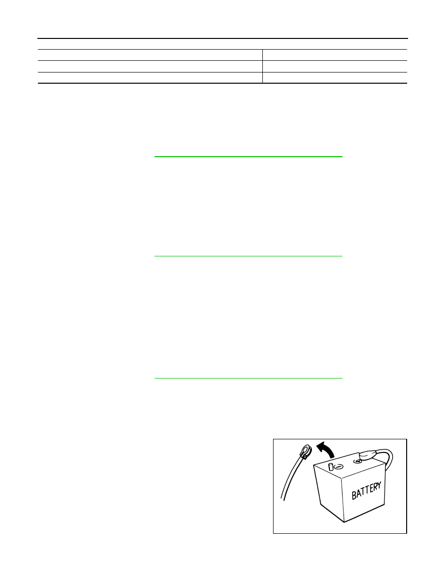
• Before connecting or disconnecting the transfer control unit

harness connector, turn ignition switch OFF and disconnect

the battery cables. Battery voltage is applied to transfer con-

trol unit even if ignition switch is turned OFF.

Indicator lamp condition

Refer procedure

When 4WD shift indicator lamp or 4LO indicator lamp is flashing.

Pattern A

Except for above.

Pattern B

SEF289H

PRECAUTIONS

DLN-85

< PRECAUTION >

[TRANSFER: TX15B]

C

E

F

G

H

I

J

K

L

M

A

B

DLN

N

O

P

• When connecting or disconnecting pin connectors into or

from transfer control unit, take care not to damage pin termi-

nals (bend or break).

When connecting pin connectors make sure that there are not

any bends or breaks on transfer control unit pin terminals.

• Before replacing transfer control unit, perform transfer con-

trol unit input/output signal inspection and make sure transfer

control unit functions properly. Refer to 

DLN-56, "Reference

Value"

.

Service Notice

INFOID:0000000009886028

• After overhaul refill the transfer with new transfer fluid.

• Check the fluid level or replace the fluid only with the vehicle parked on level ground.

• During removal or installation, keep inside of transfer clear of dust or dirt.

• Disassembly should be done in a clean work area.

• Before proceeding with disassembly, thoroughly clean the transfer. It is important to prevent the internal

parts from becoming contaminated by dirt or other foreign matter.

• Check for the correct installation status prior to removal or disassembly. If matchmarks are required, be cer-

tain they do not interfere with the function of the parts when applied.

• All parts should be carefully cleaned with a general purpose, non-flammable solvent before inspection or

reassembly.

• Check appearance of the disassembled parts for damage, deformation, and unusual wear. Replace them

with a new ones if necessary.

• Gaskets, seals and O-rings should replaced any time the transfer is disassembled.

• In principle, tighten bolts or nuts gradually in several steps working diagonally from inside to outside. If tight-

ening sequence is specified, use it.

• Observe the specified torque when assembling.

• Clean and flush the parts sufficiently and blow-dry them.

• Be careful not to damage sliding surfaces and mating surfaces.

• Use lint-free cloth or towels for wiping parts clean. Common shop rags can leave fibers that could interfere

with the operation of the transfer.

SEF291H

MEF040DB

DLN-86

< PREPARATION >

[TRANSFER: TX15B]

PREPARATION

PREPARATION

PREPARATION

Special Service Tool

INFOID:0000000009886029

The actual shapes of Kent-Moore tools may differ from those of special service tools illustrated here.

Tool number
(Kent-Moore No.)
Tool name

Description

KV32102700
(

)

Drift

• Installing mainshaft rear bearing
a: 48 mm (1.89 in) dia.
b: 41 mm (1.61 in) dia.

KV38100200
(

)

Drift

• Removing sun gear assembly and planetary 

carrier assembly

• Removing input bearing
• Installing sun gear assembly and planetary 

carrier assembly

a: 65 mm (2.56 in) dia.
b: 49 mm (1.93 in) dia.

KV38100500
(

)

Drift

• Installing front oil seal
• Installing rear oil seal
• Installing rear bearing
• Installing front bearing
a: 80 mm (3.15 in) dia.
b: 60 mm (2.36 in) dia.

KV40104830
(

)

Drift

• Installing input oil seal
a: 70 mm (2.76 in) dia.
b: 63.5 mm (2.50 in) dia.

KV40105310
(

)

Drift

• Installing dust cover
a: 89 mm (3.50 in) dia.
b: 80.7 mm (3.17 in) dia.

ST27863000
(

)

Drift

• Installing carrier bearing
a: 75 mm (2.95 in) dia.
b: 62 mm (2.44 in) dia.

ZZA0534D

ZZA1143D

ZZA0811D

ZZA1003D

ZZA1003D

ZZA1003D

PREPARATION

DLN-87

< PREPARATION >

[TRANSFER: TX15B]

C

E

F

G

H

I

J

K

L

M

A

B

DLN

N

O

P

ST30021000
(J-22912-01)
Puller

• Removing carrier bearing
• Removing front bearing
• Removing rear bearing

ST30720000
(J-25405)
Drift

• Installing input bearing
• Installing input oil seal
• Installing carrier bearing
a: 77 mm (3.03 in) dia.
b: 55 mm (2.17 in) dia.

ST30901000
(J-26010-01)
Drift

• Installing rear bearing
• Installing front bearing
a: 79 mm (3.11 in) dia.
b: 45 mm (1.77 in) dia.
c: 35.2 mm (1.38 in) dia.

ST33220000
(

)

Drift

• Installing needle bearing
a: 37 mm (1.46 in) dia.
b: 31 mm (1.22 in) dia.
c: 22 mm (0.87 in) dia.

ST33290001
(J-34286)
Puller

• Removing front oil seal
• Removing rear oil seal
• Removing metal bushing

ST33710000
(

)

Drift

• Removing needle bearing
• Removing metal bushing
• Removing rear bearing
a: 24 mm (0.94 in) dia.
b: 89 mm (3.5 in)
c: 30 mm (1.18 in) dia.

Tool number
(Kent-Moore No.)
Tool name

Description

ZZA0537D

ZZA0811D

ZZA0978D

ZZA1046D

ZZA0601D

ZZA1057D


Content   ..  126  127  128  129   ..