Nissan Titan. Manual - part 2


  Index      Nissan     Nissan Titan (2014 year) - Service and Repair Manual


Search            


Content   ..  1  2  3   ..


Nissan Titan. Manual - part 2


ACCELERATOR CONTROL SYSTEM

ACC-5

< REMOVAL AND INSTALLATION >

C

D

E

F

G

H

I

J

K

L

M

A

ACC

N

P

O

Non-Adjustable Accelerator Pedal

CAUTION:

• Do not disassemble the accelerator pedal assembly.

• Do not remove the accelerator pedal position sensor from the accelerator pedal bracket.

• Avoid damage from dropping the accelerator pedal assembly during handling.

• Keep the accelerator pedal assembly away from water.

Removal

1. Turn the ignition switch OFF and disconnect the negative battery terminal. Refer to 

PG-80, "Removal and

Installation"

.

2. Disconnect the harness connector from the accelerator pedal position sensor.
3. Remove the two upper and one lower accelerator pedal nuts. 
4. Remove the non-adjustable accelerator pedal assembly.

CAUTION:

• Do not disassemble the accelerator pedal assembly.

• Do not remove the accelerator pedal position sensor from the accelerator pedal bracket.

• Avoid damage from dropping the accelerator pedal assembly during handling.

• Keep the accelerator pedal assembly away from water.

Installation

Installation is in the reverse order of removal.

Inspection After Installation

• Check that the accelerator pedal moves smoothly within the specified range.
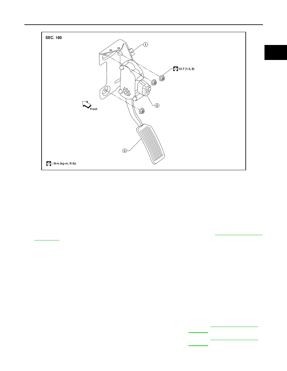
LBIA0404E

1.

Non-adjustable accelerator pedal 
A/T cable attachment bracket (part 
of the accelerator pedal assembly)

2.

Non-adjustable accelerator pedal position 
sensor (part of the accelerator pedal as-
sembly)

3.

Non-adjustable accelerator pedal 
assembly

Non-adjustable accelerator pedal – total pedal applied stroke

: Refer to 

ACC-7, "Accelerator 

Control"

.

Non-adjustable accelerator pedal – total pedal height

: Refer to 

ACC-7, "Accelerator 

Control"

.

ACC-6

< REMOVAL AND INSTALLATION >

ACCELERATOR CONTROL SYSTEM

• Depress and release the accelerator pedal to check that it returns quickly and smoothly to the original

released position.

• Perform an electrical inspection of the accelerator pedal position sensor. Refer to 

EC-128

.

CAUTION:

When the harness connector of the accelerator pedal position sensor is disconnected, perform

Accelerator Pedal Released Position Learning. Refer to 

EC-128, "Accelerator Pedal Released Posi-

tion Learning"

SERVICE DATA AND SPECIFICATIONS (SDS)

ACC-7

< SERVICE DATA AND SPECIFICATIONS (SDS) 

C

D

E

F

G

H

I

J

K

L

M

A

ACC

N

P

O

SERVICE DATA AND SPECIFICATIONS (SDS)

SERVICE DATA AND SPECIFICATIONS (SDS)

Accelerator Control

INFOID:0000000009886993

ACCELERATOR PEDAL STROKE AND TRAVEL

Unit: mm (in)

Non-adjustable accelerator pedal - total pedal applied stroke

48 (1.89)

Non-adjustable accelerator pedal - total pedal height

170.4 (6.71)

Adjustable accelerator pedal - total pedal applied stroke

48.3 (1.90)

Adjustable accelerator pedal - total pedal height

137.3 

±10 (5.41 ±0.39)

BR-1

BRAKES

C

D

E

G

H

I

J

K

L

M

SECTION 

BR

A

B

BR

N

O

P

CONTENTS

BRAKE SYSTEM

PRECAUTION ...............................................

3

PRECAUTIONS ...................................................

3

Precaution for Supplemental Restraint System 
(SRS) "AIR BAG" and "SEAT BELT PRE-TEN-
SIONER" .................................................................
..

3

Precaution for Brake System  ....................................

3

PREPARATION ............................................

4

PREPARATION ...................................................

4

Special Service Tool  .................................................

4

Commercial Service Tool  ..........................................

4

SYSTEM DESCRIPTION  ..............................

5

NOISE, VIBRATION AND HARSHNESS 
(NVH) TROUBLESHOOTING  .............................

5

NVH Troubleshooting Chart  ......................................

5

BASIC INSPECTION  ....................................

6

FRONT DISC BRAKE .........................................

6

BRAKE PAD ................................................................

6

BRAKE PAD : Inspection  ..........................................

6

DISC ROTOR ...............................................................

6

DISC ROTOR : Inspection  ........................................

6

REAR DISC BRAKE ...........................................

7

BRAKE PAD ................................................................

7

BRAKE PAD : Inspection  ..........................................

7

DISC ROTOR ...............................................................

7

DISC ROTOR : Inspection  ........................................

7

BRAKE BOOSTER  .............................................

8

Inspection ..................................................................

8

VACUUM LINES ..................................................

9

Inspection ..................................................................

9

BRAKE MASTER CYLINDER  ..........................

10

On Board Inspection ................................................

10

BRAKE TUBE AND HOSE  ...............................

11

Hydraulic Circuit  ......................................................

11

FRONT BRAKE  .........................................................

11

FRONT BRAKE : Inspection ....................................

11

REAR BRAKE ............................................................

12

REAR BRAKE : Inspection  ......................................

12

PERIODIC MAINTENANCE  ........................

13

BRAKE PEDAL .................................................

13

Inspection and Adjustment - Standard Pedal  ..........

13

Inspection and Adjustment - Adjustable Pedal  ........

14

BRAKE FLUID  ..................................................

16

On Board Inspection ................................................

16

Drain and Refill  ........................................................

16

Bleeding Brake System  ...........................................

16

REMOVAL AND INSTALLATION ...............

18

BRAKE PEDAL .................................................

18

Exploded View .........................................................

18

Removal and Installation  .........................................

19

BRAKE TUBE AND HOSE  ...............................

21

Hydraulic Circuit  ......................................................

21

Removal and Installation of Front Brake Piping 
and Brake Hose .......................................................

21

Removal and Installation of Rear Brake Piping 
and Brake Hose .......................................................

22

Inspection After Installation  .....................................

23

BRAKE MASTER CYLINDER  ..........................

25

Exploded View .........................................................

25

Removal and Installation  .........................................

25

BRAKE BOOSTER  ...........................................

27

Removal and Installation  .........................................

27


Content   ..  1  2  3   ..