Nissan Titan A60. Manual - part 931
TM-112
< DTC/CIRCUIT DIAGNOSIS >
1ST POSITION SWITCH
1ST POSITION SWITCH
CONSULT-III Reference Value in Data Monitor Mode
INFOID:0000000006159420
Diagnosis Procedure
INFOID:0000000006159421
1.
CHECK CAN COMMUNICATION LINE
Perform the self-diagnosis. Refer to
TM-36, "CONSULT-III Function (TRANSMISSION)"
.
Is any malfunction in the CAN communication indicated in the results?
YES
>> Check CAN communication line. Refer to
.
NO
>> GO TO 2.
2.
CHECK 1ST POSITION SWITCH CIRCUIT
With CONSULT-III
1. Turn ignition switch “ON”.
2. Select “ECU INPUT SIGNALS” in “DATA MONITOR” mode for “TRANSMISSION” with CONSULT-III.
3. Read out “1 POSITION SW”.
Check the signal of the 1st position switch is indicated properly.
Without CONSULT-III
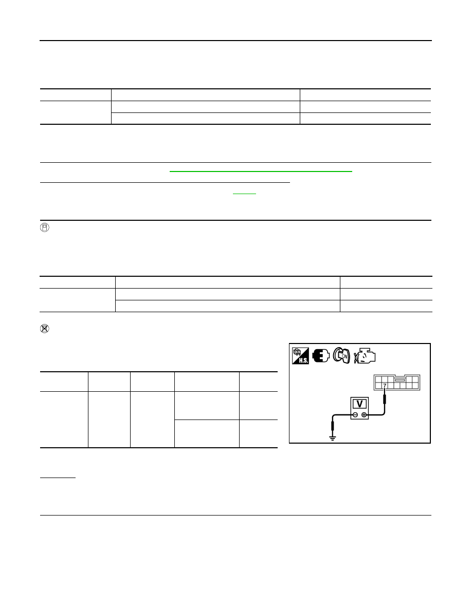
1. Turn ignition switch “ON”. (Do not start engine)
2. Check voltage between A/T shift selector connector terminal
and ground.
*1: King cab models
*2: Crew cab models
OK or NG
OK
>> GO TO 5.
NG
>> GO TO 3.
3.
CHECK 1ST POSITION SWITCH
1. Turn ignition switch “OFF”.
2. Disconnect A/T shift selector connector.
Item name
Condition
Display value
1 POSITION SW
When setting selector lever to “1” position.
ON
When setting selector lever to other positions.
OFF
Monitor item
Condition
Display value
1 POSITION SW
When setting selector lever to “1” position.
ON
When setting selector lever to other positions.
OFF
Item
Connector
Terminal
Condition
Data
(Approx.)
1st position
switch
M203
*1
M204
*2
7 - Ground
When setting selec-
tor lever to “1” posi-
tion.
0V
When setting selec-
tor lever to other po-
sitions.
Battery
voltage
JSDIA1487ZZ