Nissan Titan A60. Manual - part 929


  Index      Nissan     Nissan Titan A60 (2011 year) - Service and Repair Manual


Search            


Content   ..  927  928  929  930   ..


Nissan Titan A60. Manual - part 929


TM-104

< DTC/CIRCUIT DIAGNOSIS >

MAIN POWER SUPPLY AND GROUND CIRCUIT

OK

>> GO TO 4.

NG

>> Repair or replace damaged parts.

Component Inspection

INFOID:0000000006428173

1.

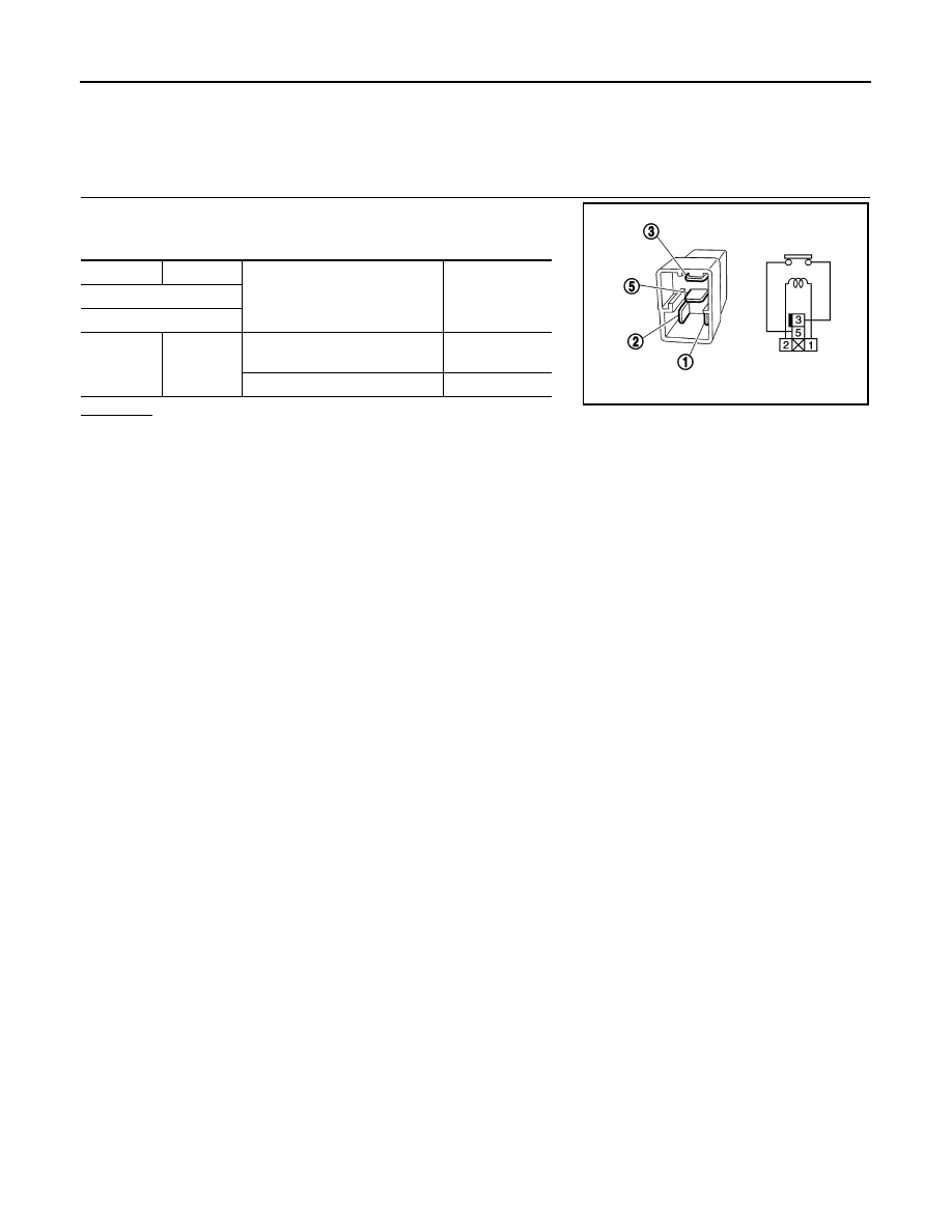
TCM (TRANSMISSION CONTROL MODULE) RELAY

Check the continuity between TCM relay terminals as per the follow-

ing conditions.

OK or NG

OK

>> INSPECTION END

NG

>> Replace the TCM relay.

+

Conditions

Continuity

TCM relay

Terminal

3

5

12 V direct current supply be-
tween terminals 1 and 2

Yes

No current supply

No

PBIB0098E

CLOSED THROTTLE POSITION AND WIDE OPEN THROTTLE POSITION CIR-

CUIT

TM-105

< DTC/CIRCUIT DIAGNOSIS >

C

E

F

G

H

I

J

K

L

M

A

B

TM

N

O

P

CLOSED THROTTLE POSITION AND WIDE OPEN THROTTLE POSITION
CIRCUIT

CONSULT-III Reference Value in Data Monitor Mode

INFOID:0000000006159408

Diagnosis Procedure

INFOID:0000000006159409

1.

CHECK CAN COMMUNICATION LINE

Perform the self-diagnosis. Refer to 

TM-36, "CONSULT-III Function (TRANSMISSION)"

.

Is a malfunction in the CAN communication indicated in the results?

YES

>> Check CAN communication line. Refer to 

TM-45

.

NO

>> GO TO 2.

2.

CHECK THROTTLE POSITION SIGNAL CIRCUIT

With CONSULT-III

1. Turn ignition switch “ON”. (Do not start engine.)

2. Select “ECU INPUT SIGNALS” in “DATA MONITOR” mode for “TRANSMISSION” with CONSULT-III.

3. Depress accelerator pedal and read out the value of “CLSD THL POS” and “W/O THL POS”.

OK or NG

OK

>> INSPECTION END

NG

>> Check the following items. If NG, repair or replace damaged parts.

• Perform the self-diagnosis for “ENGINE” with CONSULT-III.

• Open circuit or short to ground or short to power in harness or connectors.

• Pin terminals for damage or loose connection with harness connector.

Item name

Condition 

Display value

CLSD THL POS

Released accelerator pedal.

ON

Fully depressed accelerator pedal.

OFF

W/O THL POS

Fully depressed accelerator pedal.

ON

Released accelerator pedal.

OFF

Accelerator Pedal Operation

Monitor Item

CLSD THL POS

W/O THL POS

Released

ON

OFF

Fully depressed

OFF

ON

TM-106

< DTC/CIRCUIT DIAGNOSIS >

BRAKE SIGNAL CIRCUIT

BRAKE SIGNAL CIRCUIT

CONSULT-III Reference Value in Data Monitor Mode

INFOID:0000000006159410

Diagnosis Procedure

INFOID:0000000006159411

1.

CHECK CAN COMMUNICATION LINE

Perform the self-diagnosis. Refer to 

TM-36, "CONSULT-III Function (TRANSMISSION)"

.

Is a malfunction in the CAN communication indicated in the results?

YES

>> Check CAN communication line. Refer to 

TM-45, "Diagnosis Procedure"

.

NO

>> GO TO 2.

2.

CHECK STOP LAMP SWITCH CIRCUIT

With CONSULT-III

1. Turn ignition switch “ON”. (Do not start engine.)

2. Select “ECU INPUT SIGNALS” in “DATA MONITOR” mode for “TRANSMISSION” with CONSULT-III.

3. Read out ON/OFF switching action of the “BRAKE SW”.
OK or NG

OK

>> INSPECTION END

NG

>> • Column shift models, GO TO 3

• Floor shift models, GO TO 4

3.

CHECK STOP LAMP SWITCH (COLUMN SHIFT MODELS)

Check continuity between stop lamp switch terminals 3 and 4.

Check stop lamp switch after adjusting brake pedal — refer to

BR-13, "Inspection and Adjustment - Standard Pedal"

 or 

BR-14,

"Inspection and Adjustment - Adjustable Pedal"

.

OK or NG

OK

>> Check stop lamp switch circuit.

NG

>> Repair or replace stop lamp switch.

4.

CHECK STOP LAMP SWITCH (FLOOR SHIFT MODELS)

Check continuity between stop lamp switch terminals 1 and 2.

Check stop lamp switch after adjusting brake pedal — refer to

BR-13, "Inspection and Adjustment - Standard Pedal"

 or 

BR-14,

"Inspection and Adjustment - Adjustable Pedal"

.

OK or NG

OK

>> Check stop lamp switch circuit.

NG

>> Repair or replace stop lamp switch.

Item name

Condition 

Display value

BRAKE SW

Depressed brake pedal.

ON

Released brake pedal.

OFF

Condition

Continuity

When brake pedal is depressed

Yes

When brake pedal is released

No

AWDIA0419ZZ

Condition

Continuity

When brake pedal is depressed

Yes

When brake pedal is released

No

PBIB0118E

TOW MODE SWITCH

TM-107

< DTC/CIRCUIT DIAGNOSIS >

C

E

F

G

H

I

J

K

L

M

A

B

TM

N

O

P

TOW MODE SWITCH

Description

INFOID:0000000006159412

When tow mode switch is “ON”, tow mode switch signals are sent to TCM from combination meter by CAN

communication line.Then it`s a tow mode condition.

Diagnosis Procedure

INFOID:0000000006159413

1.

CHECK CAN COMMUNICATION LINE

Perform the self-diagnosis. Refer to 

TM-36, "CONSULT-III Function (TRANSMISSION)"

.

Is any malfunction in the CAN communication indicated in the results?

YES

>> Check CAN communication line. Refer to 

TM-45

.

NO

>> GO TO 2.

2.

CHECK POWER SOURCE

1. Turn ignition switch “ON”. (Do not start engine.)

2. Check the voltage between tow mode switch connector M67 ter-

minal 1 and ground.

OK or NG

OK

>> INSPECTION END

NG

>> GO TO 3.

3.

CHECK TOW MODE SWITCH

1. Turn ignition switch “OFF”.

2. Disconnect tow mode switch connector.

3. Check continuity between tow mode switch connector M67 ter-

minals 1 and 2.

OK or NG

OK

>> GO TO 4.

NG

>> Repair or replace tow mode switch.

4.

DETECT MALFUNCTIONING ITEM

Check the following items. If any items are damaged, repair or replace damaged parts.

• Harness for short or open between combination meter connector terminal 35 and tow mode switch connec-

tor terminal 1.

• Harness for short or open between tow mode switch connector terminal 2 and ground.
OK or NG

OK

>> GO TO 5.

NG

>> Repair or replace damaged parts.

5.

CHECK COMBINATION METER

Check the combination meter. Refer to 

TM-6, "Work Flow"

.

OK or NG

OK

>> INSPECTION END

NO

>> Repair or replace damaged parts.

Condition

Tow mode 

switch

Data (Approx.)

When ignition switch is turned to “ON”

ON

0V

OFF

Battery voltage

SCIA5156E

Condition

Continuity

Tow mode switch “ON”

Yes

Tow mode switch “OFF”

No

JSDIA1502ZZ


Content   ..  927  928  929  930   ..