Nissan Titan A60. Manual - part 917


  Index      Nissan     Nissan Titan A60 (2011 year) - Service and Repair Manual


Search            


Content   ..  915  916  917  918   ..


Nissan Titan A60. Manual - part 917


TM-56

< DTC/CIRCUIT DIAGNOSIS >

P0720 OUTPUT SPEED SENSOR

 WITH GST

Follow the procedure “With CONSULT-III”.

Diagnosis Procedure

INFOID:0000000006159282

1.

CHECK INPUT SIGNAL

With CONSULT-III

1. Turn ignition switch “ON”.

2. Select “ECU INPUT SIGNALS” in “DATA MONITOR” mode for “TRANSMISSION” with CONSULT-III.

3. Start the engine.

4. Read out the value of “VHCL/S SE-A/T” while driving.

Check the value changes according to driving speed.

OK or NG

OK

>> GO TO 6.

NG

>> GO TO 2.

2.

CHECK TCM POWER SUPPLY AND GROUND CIRCUIT

Check TCM power supply and ground circuit. Refer to 

TM-101, "Diagnosis Procedure"

.

OK or NG

OK

>> GO TO 3.

NG

>> Repair or replace damaged parts.

3.

DETECT MALFUNCTIONING ITEM

Check the following items:

• The A/T assembly harness connector pin terminals for damage or loose connection with harness connector.
OK or NG

OK

>> GO TO 4.

NG

>> Repair or replace damaged parts.

4.

CHECK SUB-HARNESS

1. Remove control valve with TCM. Refer to 

TM-197, "Control Valve with TCM"

.

2. Disconnect transmission range switch connector and TCM connector.

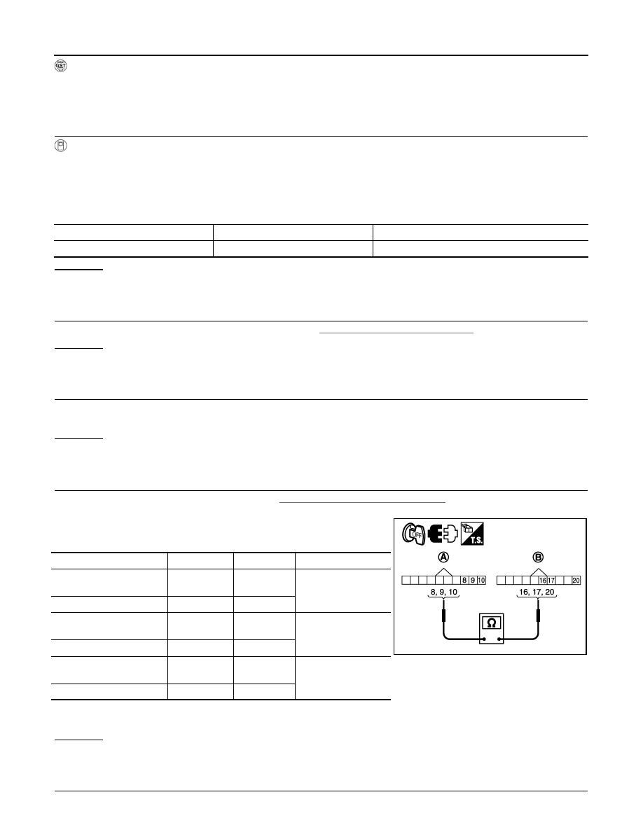
3. Check continuity between transmission range switch connector

(A) terminals and TCM connector (B) terminals.

4. If OK, check harness for short to ground and short to power.

5. Reinstall any part removed.
OK or NG

OK

>> GO TO 5.

NG

>> Replace open circuit or short to ground and short to power in harness or connectors.

5.

REPLACE THE OUTPUT SPEED SENSOR AND CHECK DTC

Item name

Condition 

Display value (km/h)

VHCL/S SE-A/T

 During driving

 Approximately matches the speedometer reading.

Item

Connector Terminal

Continuity

Transmission range switch 

connector

F505

8

Yes

TCM connector

F503

20

Transmission range switch 

connector

F505

9

Yes

TCM connector

F503

17

Transmission range switch 

connector

F505

10

Yes

TCM connector

F503

16

JSDIA1329GB

P0720 OUTPUT SPEED SENSOR

TM-57

< DTC/CIRCUIT DIAGNOSIS >

C

E

F

G

H

I

J

K

L

M

A

B

TM

N

O

P

1. Replace the output speed sensor. Refer to 

TM-224, "Disassembly"

.

2. Perform “DTC Confirmation Procedure”. Refer to 

TM-55, "DTC Confirmation Procedure"

.

OK or NG

OK

>> INSPECTION END

NG

>> Replace the control valve with TCM. Refer to 

TM-197, "Control Valve with TCM"

.

6.

CHECK DTC

Perform “DTC Confirmation Procedure”.

• Refer to 

TM-55, "DTC Confirmation Procedure"

.

OK or NG

OK

>> INSPECTION END

NG

>> GO TO 2.

TM-58

< DTC/CIRCUIT DIAGNOSIS >

P0725 ENGINE SPEED

P0725 ENGINE SPEED

Description

INFOID:0000000006159283

The engine speed signal is sent from the ECM to the TCM.

CONSULT-III Reference Value in Data Monitor Mode

INFOID:0000000006159284

On Board Diagnosis Logic

INFOID:0000000006159285

• This is not an OBD-II self-diagnostic item.

• Diagnostic trouble code “P0725” with CONSULT-III or 16th judgment flicker without CONSULT-III  is

detected when TCM does not receive the ignition signal from ECM during engine cranking or running.

Possible Cause

INFOID:0000000006159286

Harness or connectors

(The ECM to the TCM circuit is open or shorted.)

DTC Confirmation Procedure

INFOID:0000000006159287

CAUTION:

Always drive vehicle at a safe speed.

NOTE:

If “DTC Confirmation Procedure” has been previously performed, always turn ignition switch “OFF”

and wait at least 10 seconds before performing the next test.

After the repair, perform the following procedure to confirm the malfunction is eliminated.

 WITH CONSULT-III

1. Turn ignition switch “ON” and select “DATA MONITOR” mode for “TRANSMISSION” with CONSULT-III.

2. Start engine and maintain the following conditions for at least 10 consecutive seconds.

VHCL/S SE-A/T: 10 km/h (6 MPH) or more

ACCELE POSI: More than 1/8

SLCT LVR POSI: “D” position 

3. If DTC is detected, go to 

TM-58, "Diagnosis Procedure"

.

Diagnosis Procedure

INFOID:0000000006159288

1.

CHECK CAN COMMUNICATION LINE

Perform the self-diagnosis. Refer to 

TM-36, "CONSULT-III Function (TRANSMISSION)"

.

Is a malfunction in the CAN communication indicated in the results?

YES

>> Check CAN communication line. Refer to 

TM-45

.

NO

>> GO TO 2.

2.

CHECK DTC WITH TCM

With CONSULT-III

1. Start engine.

2. Select “ECU INPUT SIGNALS” in “DATA MONITOR” mode for “TRANSMISSION” with CONSULT-III.

3. While monitoring engine speed, check for engine speed change corresponding to wide-open throttle posi-

tion signal.

OK or NG

OK

>> GO TO 3.

Item name

Condition 

Display value (rpm)

ENGINE SPEED

 Engine running

 Closely matches the tachometer reading.

Item name

Condition 

Display value (rpm)

ENGINE SPEED

 Engine running

 Closely matches the tachometer reading.

P0725 ENGINE SPEED

TM-59

< DTC/CIRCUIT DIAGNOSIS >

C

E

F

G

H

I

J

K

L

M

A

B

TM

N

O

P

NG

>> Check the ignition signal circuit.

• Refer to 

EC-453, "Diagnosis Procedure"

.

3.

CHECK DTC

Perform "DTC Confirmation Procedure". 

• Refer to 

TM-58, "DTC Confirmation Procedure"

.

OK or NG

OK

>> INSPECTION END

NG

>> GO TO 4.

4.

CHECK TCM POWER SUPPLY AND GROUND CIRCUIT

Check TCM power supply and ground circuit. Refer to 

TM-101, "Diagnosis Procedure"

.

OK or NG

OK

>> GO TO 5.

NG

>> Repair or replace damaged parts.

5.

DETECT MALFUNCTIONING ITEM

Check the following items:

• The A/T assembly harness connector pin terminals for damage or loose connection with harness connector.
OK or NG

OK

>> Replace the control valve with TCM. Refer to 

TM-197, "Control Valve with TCM"

.

NG

>> Repair or replace damaged parts.


Content   ..  915  916  917  918   ..