Nissan Titan A60. Manual - part 894
STEERING COLUMN
ST-13
< UNIT REMOVAL AND INSTALLATION >
C
D
E
F
H
I
J
K
L
M
A
B
ST
N
O
P
Floor Shift Model
CAUTION:
• Any time the ignition switch has been disconnected, removed or installed, the keys must be re-regis-
tered in the BCM. Refer to Consult-III operations IVIS/NVIS.
• Care must be taken not to give axial impact to steering column assembly during removal and instal-
lation.
• Care must be taken not to move steering gear during removal of steering column assembly.
REMOVAL
1. Remove spiral cable from steering column assembly with combination switches attached. Refer to
2. Remove tilt lever knob from tilt lever by inserting a suitable tool
into slot of tilt lever knob, then depress tab and withdraw tilt lever
knob.
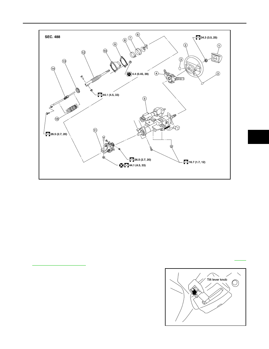
AWGIA0117GB
1.
Driver air bag module
2.
Steering wheel
3.
Steering wheel side cover
4.
Combination switch and spiral cable 5.
Steering column assembly
6.
Collar
7.
Hole cover seal
8.
Clamp
9.
Hole cover mounting plate
10. Hole cover
11. Upper joint
12. Upper shaft
13. Boot clamp
14. Lower joint shaft
15. Boot and clips (plastic)
WGIA0061E