Nissan Titan A60. Manual - part 864
SN-24
< SYMPTOM DIAGNOSIS >
SONAR SYSTEM SYMPTOMS
SYMPTOM DIAGNOSIS
SONAR SYSTEM SYMPTOMS
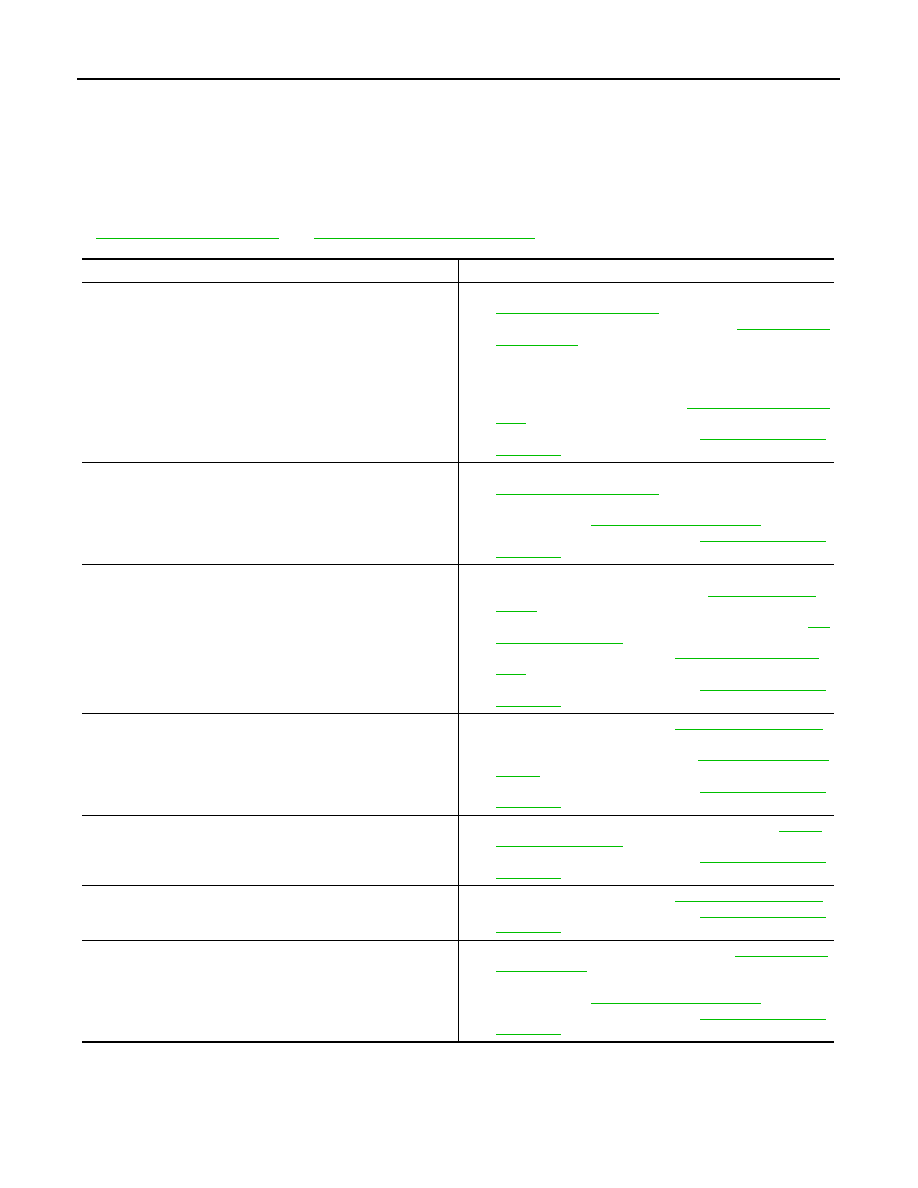
Symptom Table
INFOID:0000000006159220
NOTE:
Always perform Preliminary Check and Self-Diagnosis Function before diagnosing vehicle by symptom. Refer
to
SN-7, "Self-Diagnosis Function"
.
Symptom
Repair order
When the transmission gear selector lever is in the R position and
the sonar system is ON, the rear sonar system does not operate.
1.
Check sonar control unit power and ground circuits. Refer to
.
2.
Check transmission range switch. Refer to
.
3.
Check back-up lamp relay.
4.
Check related harness and connections for back-up lamp re-
lay.
5.
Check rear sonar buzzer. Refer to
.
6.
Replace sonar control unit. Refer to
.
Sonar Control Unit will not enter Diagnostic Mode.
1.
Check sonar control unit power and ground circuits. Refer to
.
2.
Check harness and connections for sonar system OFF
switch. Refer to
3.
Replace sonar control unit. Refer to
.
Buzzer sounds although there are no obstacles within the detec-
tion range (false detection).
1.
Check all sonar sensors for misalignment or damage (in-
cluding bumper and fascia). Refer to
2.
Check all sonar sensors for dirt or ice buildup. Refer to
3.
.
4.
Replace sonar control unit. Refer to
.
When sonar system is ON, the sonar system OFF indicator lamp
lights up and the sonar buzzer sounds intermittently (for about 4
seconds).
1.
2.
Check harnesses between sonar sensors and sonar control
unit for an open condition. Refer to
3.
Replace sonar control unit. Refer to
.
The sonar system still operates when the sonar system OFF indi-
cator lamp is ON.
1.
Check sonar system OFF indicator lamp. Refer to
.
2.
Replace sonar control unit. Refer to
.
The sonar sensors do not detect objects within the detectable
range (intermittent operation).
1.
2.
Replace sonar control unit. Refer to
.
When the sonar system is OFF, the OFF indicator does not light
and the rear sonar buzzer does not sound.
1.
Check sonar system OFF switch. Refer to
2.
Check harness and connections for sonar system OFF
switch. Refer to
3.
Replace sonar control unit. Refer to
.