Nissan Titan A60. Manual - part 824


  Index      Nissan     Nissan Titan A60 (2011 year) - Service and Repair Manual


Search            


Content   ..  822  823  824  825   ..


Nissan Titan A60. Manual - part 824


SHOCK ABSORBER

RSU-11

< REMOVAL AND INSTALLATION >

C

D

F

G

H

I

J

K

L

M

A

B

RSU

N

O

P

SHOCK ABSORBER

Removal and Installation

INFOID:0000000006161781

REMOVAL

1. Support the rear final drive and suspension assembly using a suitable jack.
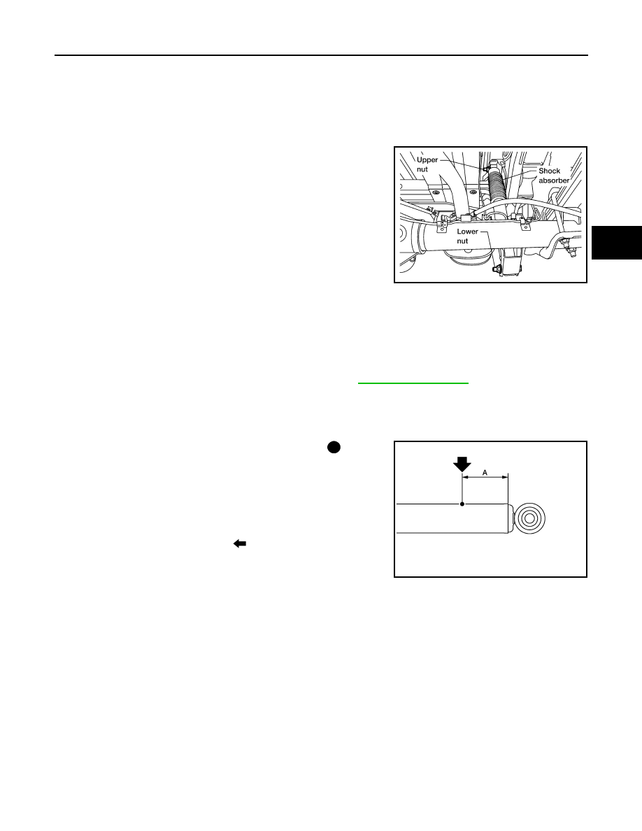
2. Remove the shock absorber upper and lower nuts and bolts

using power tool.

3. Remove the shock absorber.

INSPECTION AFTER REMOVAL

Inspect the shock absorber for any oil leaks, cracks, or deformations. Replace the shock absorber as neces-

sary.

INSTALLATION

Installation is in the reverse order of removal.

Disposal

INFOID:0000000006161782

1. Set shock absorber horizontally with the piston rod fully extended.
2. Drill 2 – 3 mm (0.08 – 0.12 in) hole at the position ( ) from top

as shown in the figure to release gas gradually.

CAUTION:

• Wear eye protection (safety glasses).

• Wear gloves.

• Be careful with metal chips or oil blown out by the com-

pressed gas.

NOTE:
• Drill vertically in this direction (

).

• Directly to the outer tube avoiding brackets.

• The gas is clear, colorless, odorless, and harmless.

3. Position the drilled hole downward and drain oil by moving the piston rod several times.

CAUTION:

Dispose of drained oil according to the law and local regulations.

LEIA0104E

Shock absorber upper and lower nuts

: Refer to 

RSU-6, "Component"

.

A

: 20 – 30 mm (0.79 – 1.18 in)

JPEIA0161ZZ

RSU-12

< SERVICE DATA AND SPECIFICATIONS (SDS) 

SERVICE DATA AND SPECIFICATIONS (SDS)

SERVICE DATA AND SPECIFICATIONS (SDS)

SERVICE DATA AND SPECIFICATIONS (SDS)

General Specification (Rear)

INFOID:0000000006161783

Wheelarch Height (Unladen*1)

INFOID:0000000006161784

Unit: mm (in)

*1: Fuel, radiator coolant and engine oil full. Spare tire, jack, hand tools and mats in designated positions.
*2: Without tow package.
*3: With tow package.

Suspension type

Rigid axle with semi-elliptic leaf spring

Shock absorber type

Double-acting hydraulic

Drive 
type

2WD

4WD*2

4WD*3

Wheel 
base

Short

Long

Short

Long

Short

Long

Body

King 

Cab

Crew 

Cab

King 

Cab

Crew 

Cab

King 

Cab

Crew 

Cab

King 

Cab

Crew 

Cab

King 

Cab

Crew 

Cab

King 

Cab

Crew 

Cab

Front 
wheel
arch 
height 
(Hf)

P265/
70R18

912 

(35.91)

914 

(35.98)

912 

(35.91)

914 

(35.98)

949 

(37.36)

951 

(37.44)

949 

(37.36)

951 

(37.44)

949 

(37.36)

951 

(37.44)

949 

(37.36)

951 

(37.44)

P275/
70R18

922 

(36.30)

925 

(36.42)

922 

(36.30)

925 

(36.42)

960 

(37.80)

962 

(37.87)

959 

(37.76)

962 

(37.87)

960 

(37.80)

962 

(37.87)

959 

(37.76)

962 

(37.87)

P275/
60R20

917 

(36.10)

919 

(36.18)

917 

(36.10)

920 

(36.22)

955 

(37.60)

957 

(37.68)

954 

(37.56)

957 

(37.68)

955 

(37.60)

957 

(37.68)

954 

(37.56)

957 

(37.68)

Rear 
wheel
arch 
height 
(Hr)

P265/
70R18

952 

(3748)

954 

(37.56)

950 

(37.40)

951 

(37.44)

991 

(39.02)

994 

(39.13)

989 

(38.94)

991 

(39.02)

991 

(39.02)

993 

(39.09)

989 

(38.94)

991 

(39.02)

P275/
70R18

962 

(37.87)

965 

(37.99)

960 

(37.80)

962 

(37.87)

1002 

(39.45)

1004 

(39.53)

1000 

(39.37)

1002 

(39.45)

1001 

(39.41)

1004 

(39.53)

1000 

(39.37)

1002 

(39.45)

P275/
60R20

957 

(37.68)

959 

(37.76)

955 

(37.60)

956 

(37.64)

996 

(39.21)

999 

(39.33)

995 

(39.17)

996 

(39.21)

996 

(39.21)

998 

(39.29)

995 

(39.17)

996 

(39.21)

LEIA0085E

SB-2

< PRECAUTION >

PRECAUTIONS

PRECAUTION

PRECAUTIONS

Precaution for Supplemental Restraint System (SRS) "AIR BAG" and "SEAT BELT 
PRE-TENSIONER"

INFOID:0000000006158501

The Supplemental Restraint System such as “AIR BAG” and “SEAT BELT PRE-TENSIONER”, used along

with a front seat belt, helps to reduce the risk or severity of injury to the driver and front passenger for certain

types of collision. This system includes seat belt switch inputs and dual stage front air bag modules. The SRS

system uses the seat belt switches to determine the front air bag deployment, and may only deploy one front

air bag, depending on the severity of a collision and whether the front occupants are belted or unbelted.

Information necessary to service the system safely is included in the SR and SB section of this Service Man-

ual.

WARNING:

• To avoid rendering the SRS inoperative, which could increase the risk of personal injury or death in

the event of a collision which would result in air bag inflation, all maintenance must be performed by

an authorized NISSAN/INFINITI dealer.

• Improper maintenance, including incorrect removal and installation of the SRS, can lead to personal

injury caused by unintentional activation of the system. For removal of Spiral Cable and Air Bag

Module, see the SR section.

• Do not use electrical test equipment on any circuit related to the SRS unless instructed to in this

Service Manual. SRS wiring harnesses can be identified by yellow and/or orange harnesses or har-

ness connectors.

PRECAUTIONS WHEN USING POWER TOOLS (AIR OR ELECTRIC) AND HAMMERS

WARNING:

• When working near the Airbag Diagnosis Sensor Unit or other Airbag System sensors with the Igni-

tion ON or engine running, DO NOT use air or electric power tools or strike near the sensor(s) with a

hammer. Heavy vibration could activate the sensor(s) and deploy the air bag(s), possibly causing

serious injury.

• When using air or electric power tools or hammers, always switch the Ignition OFF, disconnect the

battery, and wait at least 3 minutes before performing any service.

Precaution for Seat Belt Service

INFOID:0000000006158502

CAUTION:

• Before removing the seat belt pre-tensioner assembly, turn the ignition switch OFF, disconnect both

battery cables and wait at least 3 minutes.

• After replacing or reinstalling seat belt pre-tensioner assembly, or reconnecting seat belt pre-ten-

sioner assembly connector, ensure entire SRS operates properly. Refer to 

SRC-13, "SRS Operation

Check"

.

• Do not disassemble buckle or seat belt assembly.

• Do not reuse seat belt anchor bolts after removal. Replace with new ones.

• Replace anchor bolts if they are deformed or worn out.

• Never oil tongue and buckle.

• If any component of seat belt assembly is questionable, do not repair. Replace the whole seat belt

assembly.

• If webbing is cut, frayed, or damaged, replace seat belt assembly.

• When replacing seat belt assembly, use a genuine NISSAN seat belt assembly.

AFTER A COLLISION

WARNING:

• Inspect all seat belt assemblies including retractors and attaching hardware after any collision.

• NISSAN recommends that all seat belt assemblies in use during a collision be replaced unless the

collision was minor and the belts show no damage and continue to operate properly. Failure to do so

could result in serious personal injury in an accident. Seat belt assemblies not in use during a colli-

sion should also be replaced if either damage or improper operation is noted. Seat belt pre-tensioner

should be replaced even if the seat belts are not in use during a frontal collision in which the air bags

are deployed.

Replace any seat belt assembly (including anchor bolts) if:


Content   ..  822  823  824  825   ..