Nissan Titan A60. Manual - part 811


  Index      Nissan     Nissan Titan A60 (2011 year) - Service and Repair Manual


Search            


Content   ..  809  810  811  812   ..


Nissan Titan A60. Manual - part 811


POWER SUPPLY AND GROUND CIRCUIT

RF-11

< DTC/CIRCUIT DIAGNOSIS >

C

D

E

F

G

H

I

J

L

M

A

B

RF

N

O

P

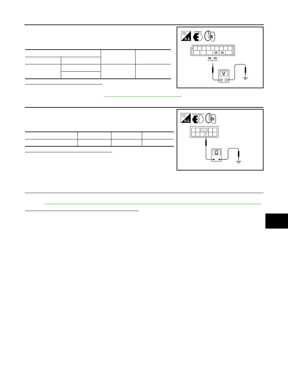
1. Connect BCM connector M20.

2. Turn ignition switch ON.

3. Check voltage between BCM connector M20 and ground.

Is the voltage reading as specified?

YES

>> Check condition of harness and connector.

NO

>> Replace BCM. Refer to 

BCS-53, "Removal and Installation"

.

4.

 CHECK GROUND CIRCUIT

1. Turn ignition switch OFF.

2. Check continuity between sunroof motor assembly connector

R4 terminal 7 and ground.

Is the continuity test result as specified?

YES

>> Power supply and ground circuits are OK.

NO

>> Repair or replace harness.

SUNROOF MOTOR ASSEMBLY : Special Repair Requirement

INFOID:0000000006163226

1.

 PERFORM INITIALIZATION PROCEDURE

Perform initialization procedure. 

Refer to 

RF-5, "ADDITIONAL SERVICE WHEN REPLACING CONTROL UNIT : Special Repair Requirement"

.

Does the sunroof motor assembly operate properly?

YES

>> Repair is complete.

NO

>> Check fitting adjustment.

(+)

(–)

Voltage

Connector

Terminal 

M20

68

Ground

Battery voltage

69

ALKIA0871ZZ

Connector

Terminal

Continuity 

R4

7

Ground

Yes

ALKIA0869ZZ

RF-12

< DTC/CIRCUIT DIAGNOSIS >

SUNROOF SWITCH CIRCUIT

SUNROOF SWITCH CIRCUIT

Description

INFOID:0000000006163227

The BCM supplies power to the integrated CPU of the sunroof motor assembly. The tilt and slide functions of

the sunroof motor assembly is controlled by the sunroof switch. 

Component Function Check

INFOID:0000000006163228

1.

 CHECK SUNROOF MOTOR FUNCTION

Do tilt up/down & slide open/close functions operate normally with sunroof switch?
Is the inspection result normal?

YES

>> Sunroof motor assembly is OK.

NO

>> Refer to 

RF-10, "SUNROOF MOTOR ASSEMBLY : Diagnosis Procedure"

.

Diagnosis Procedure

INFOID:0000000006163229

Regarding Wiring Diagram information, refer to 

RF-28, "Wiring Diagram"

.

1.

 CHECK SUNROOF SWITCH INPUT SIGNAL 

1. Turn ignition switch ON.

2. Check voltage between sunroof switch connector and ground.

Are the voltage measurements as specified?

YES

>> Sunroof switch is operating normally. 

NO

>> GO TO 2

2.

 CHECK SUNROOF SWITCH CIRCUITS

1. Turn ignition switch OFF.

2. Disconnect sunroof motor assembly connector R4 and sunroof

switch connector R104.

3. Check continuity between sunroof switch connector R104 (A)

and sunroof motor assembly connector R4 (B).

Connector

Terminals

Sunroof switch position

Voltage (V)

(Approx.)

(+)

(–)

R104

1

2

SLIDE CLOSE

0V

Other than above

Battery voltage

3

SLIDE OPEN

0V

Other than above

Battery voltage

4

TILT UP

0V

Other than above

Battery voltage

6

TILT DOWN

0V

Other than above

Battery voltage

ALKIA1041GB

ALKIA0873ZZ

SUNROOF SWITCH CIRCUIT

RF-13

< DTC/CIRCUIT DIAGNOSIS >

C

D

E

F

G

H

I

J

L

M

A

B

RF

N

O

P

4. Check continuity between sunroof switch connector R104 (A) and ground. 

Are the continuity test results as specified?

YES

>> GO TO 3

NO

>> Repair harness or connector.

3.

 CHECK SUNROOF SWITCH

1. Check continuity between sunroof switch terminals.

Are the continuity test results as specified?

YES

>> Sunroof switch is operating normally.

NO

>> Replace sunroof switch (map lamp assembly). Refer to 

INL-72, "Removal and Installation"

.

A

B

Continuity

Connector

Terminal

Connector

Terminal

R104

1

R4

3

Yes

2

8

3

9

4

4

6

10

A

Continuity

Connector

Terminal

R104

1

Ground

No

2

3

4

6

Terminals

Sunroof switch position

Continuity

1

2

SLIDE CLOSE

Yes

Other than above

No

3

SLIDE OPEN

Yes

Other than above

No

4

TILT UP

Yes

Other than above

No

6

TILT DOWN

Yes

Other than above

No

ALKIA0874ZZ

RF-14

< DTC/CIRCUIT DIAGNOSIS >

DOOR SWITCH

DOOR SWITCH

Description

INFOID:0000000006163233

Detects door open/close condition.

Component Function Check

INFOID:0000000006163234

1.

CHECK FUNCTION

With CONSULT-III

Check door switches in data monitor mode with CONSULT-III.

Is the inspection result normal?

YES

>> Door switch is OK.

NO

>> Refer to 

RF-14, "Diagnosis Procedure"

.

Diagnosis Procedure

INFOID:0000000006163235

Regarding Wiring Diagram information, refer to 

RF-28, "Wiring Diagram"

.

1.

CHECK DOOR SWITCHES INPUT SIGNAL

With CONSULT-III

Check door switches ("DOOR SW-DR" and "DOOR SW-AS") in DATA MONITOR mode with CONSULT–III.

Refer to 

BCS-16, "DOOR LOCK : CONSULT-III Function (BCM - DOOR LOCK)"

.

• When doors are open:

• When doors are closed:

Without CONSULT-III

Check voltage between BCM connector M18 or M19 terminals 12, 47 and ground.

Is the inspection result normal?

YES

>> Door switch circuit is OK.

NO

>> GO TO 2

2.

CHECK DOOR SWITCH CIRCUIT

1. Turn ignition switch OFF.

Monitor item

Condition

DOOR SW-DR

CLOSE 

→ OPEN: OFF → ON

DOOR SW-AS

DOOR SW-DR

:ON

DOOR SW-AS

:ON

DOOR SW-DR

:OFF

DOOR SW-AS

:OFF

Connector

Item

Terminals

Condition

Voltage (V)

(Approx.)

(+)

(–)

M19

Front door 

switch LH

47

Ground

Open

Closed

0

Battery voltage

M18

Front door 

switch RH

12


Content   ..  809  810  811  812   ..