Nissan Titan A60. Manual - part 754
PCS
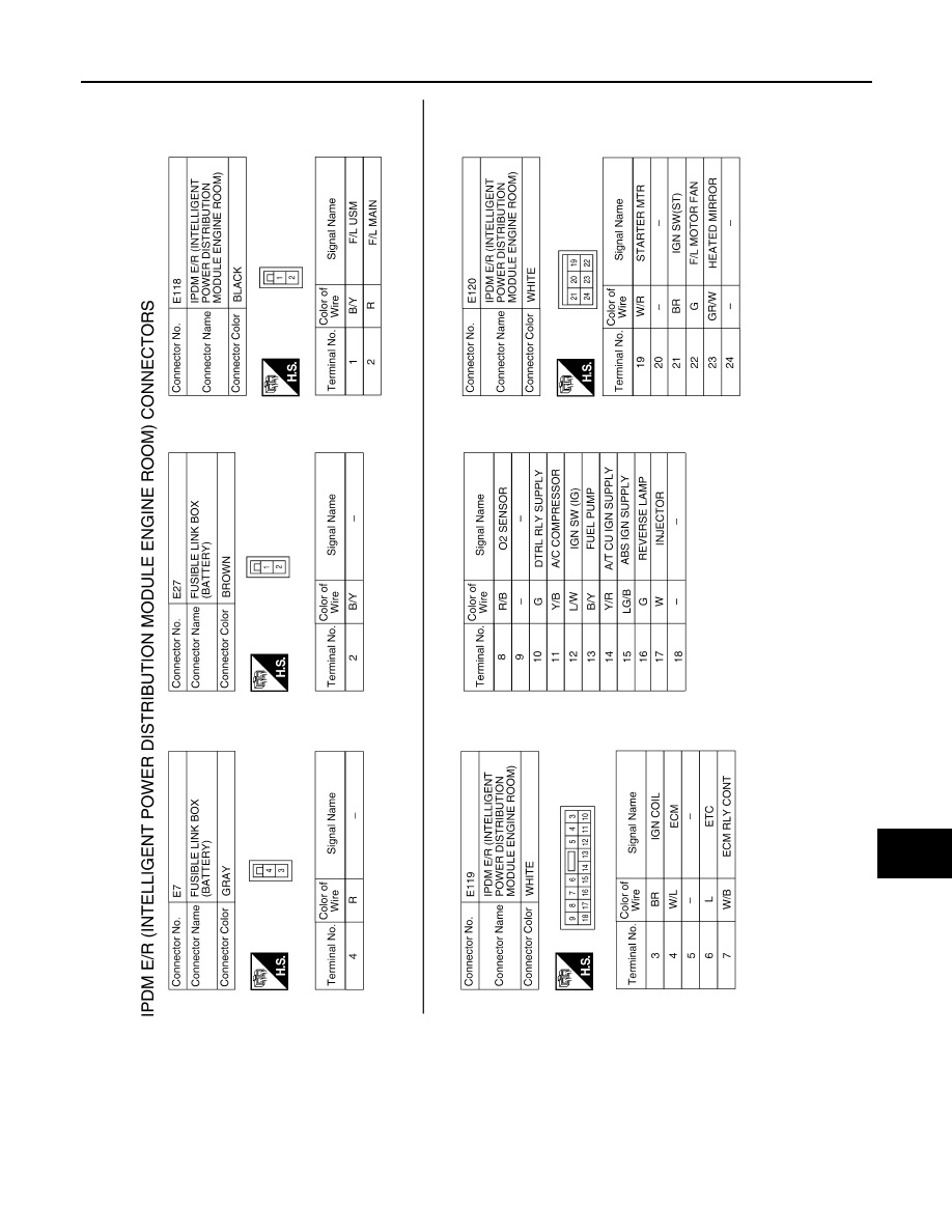
IPDM E/R (INTELLIGENT POWER DISTRIBUTION MODULE ENGINE ROOM)
PCS-25
< WIRING DIAGRAM >
[IPDM E/R]
C
D
E
F
G
H
I
J
K
L
B
A
O
P
N
ABMIA2491GB
|
|
|
PCS IPDM E/R (INTELLIGENT POWER DISTRIBUTION MODULE ENGINE ROOM) PCS-25 < WIRING DIAGRAM > [IPDM E/R] C D E F G H I J K L B A O P N ABMIA2491GB |