Nissan Titan A60. Manual - part 752
 

  Index      Nissan     Nissan Titan A60 (2011 year) - Service and Repair Manual


Search            


Content   ..  750  751  752  753   ..


Nissan Titan A60. Manual - part 752


PCS

IPDM E/R (INTELLIGENT POWER DISTRIBUTION MODULE ENGINE ROOM)

PCS-17

< ECU DIAGNOSIS INFORMATION >

[IPDM E/R]

C

D

E

F

G

H

I

J

K

L

B

A

O

P

N

ECU DIAGNOSIS INFORMATION

IPDM E/R (INTELLIGENT POWER DISTRIBUTION MODULE ENGINE
ROOM)

Reference Value

INFOID:0000000006158390

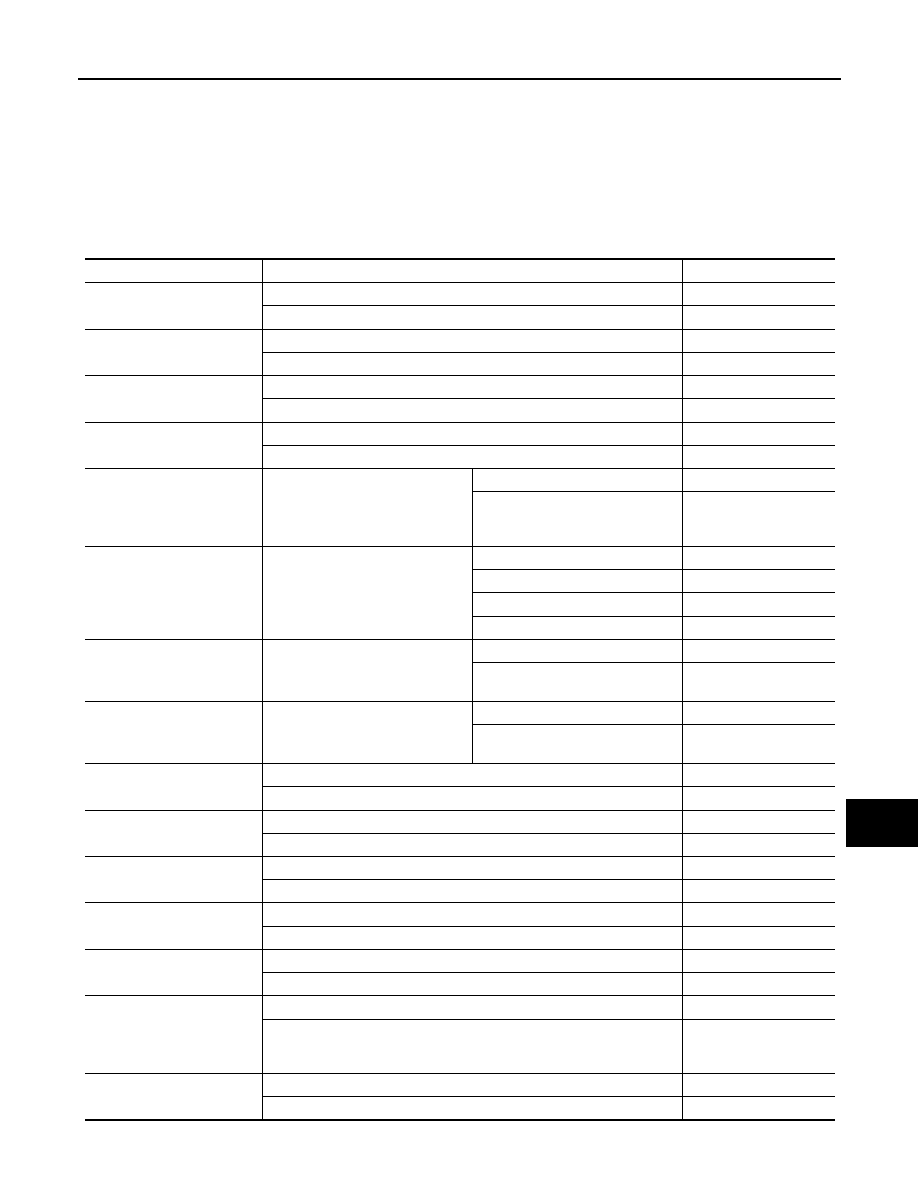
VALUES ON THE DIAGNOSIS TOOL

*: If equipped

Monitor Item

Condition

Value/Status

A/C COMP REQ

A/C switch OFF

OFF

A/C switch ON

ON

TAIL&CLR REQ

Lighting switch OFF

OFF

Lighting switch 1ST, 2ND, HI or AUTO (Light is illuminated)

ON

HL LO REQ

Lighting switch OFF

OFF

Lighting switch 2ND HI or AUTO (Light is illuminated)

ON

HL HI REQ

Lighting switch OFF

OFF

Lighting switch HI

ON

FR FOG REQ*

Lighting switch 2ND or AUTO (Light 
is illuminated)

Front fog lamp switch OFF

OFF

• Front fog lamp switch ON
• Daytime light activated (Canada 

only)

ON

FR WIP REQ

Ignition switch ON

Front wiper switch OFF

STOP

Front wiper switch INT

1LOW

Front wiper switch LO

LOW

Front wiper switch HI

HI

WIP AUTO STOP

Ignition switch ON

Front wiper stop position

STOP P

Any position other than front wiper 
stop position

ACT P

WIP PROT

Ignition switch ON

Front wiper operates normally

OFF

Front wiper stops at fail-safe opera-
tion

BLOCK

ST RLY REQ

Ignition switch OFF or ACC

OFF

Ignition switch START

ON

IGN RLY

Ignition switch OFF or ACC

OFF

Ignition switch ON

ON

RR DEF REQ*

Rear defogger switch OFF

OFF

Rear defogger switch ON

ON

OIL P SW

Ignition switch OFF, ACC or engine running

OPEN

Ignition switch ON

CLOSE

DTRL REQ

Daytime light system requested OFF with CONSULT-III.

OFF

Daytime light system requested ON with CONSULT-III.

ON

THFT HRN REQ

Not operated

OFF

• Panic alarm is activated
• Horn is activated with VEHICLE SECURITY (THEFT WARNING) SYS-

TEM

ON

HORN CHIRP

Not operated

OFF

Door locking with keyfob (horn chirp mode)

ON

PCS-18

< ECU DIAGNOSIS INFORMATION >

[IPDM E/R]

IPDM E/R (INTELLIGENT POWER DISTRIBUTION MODULE ENGINE ROOM)

Terminal Layout

INFOID:0000000006158391

NOTE:

Numbers preceded by an "F" represent the fuse numbers imprinted on the IPDM E/R.  The other numbers rep-

resent the fuse numbers as they appear in the wiring diagrams.

Physical Values

INFOID:0000000006158392

PHYSICAL VALUES

AAMIA0386GB

PCS

IPDM E/R (INTELLIGENT POWER DISTRIBUTION MODULE ENGINE ROOM)

PCS-19

< ECU DIAGNOSIS INFORMATION >

[IPDM E/R]

C

D

E

F

G

H

I

J

K

L

B

A

O

P

N

Terminal

Wire

color

Signal name

Signal 

input/

output

Measuring condition

Reference value

(Approx.)

Igni-

tion 

switch

Operation or condition

1

B/Y

Battery power supply

Input

OFF

Battery voltage

2

R

Battery power supply

Input

OFF

Battery voltage

3

BR

ECM relay

Output

Ignition switch ON or START

Battery voltage

Ignition switch OFF or ACC

0V

4

W/L

ECM relay

Output

Ignition switch ON or START

Battery voltage

Ignition switch OFF or ACC

0V

6

L

Throttle control mo-
tor relay

Output

Ignition switch ON or START

Battery voltage

Ignition switch OFF or ACC

0V

7

W/B

ECM relay control

Input

Ignition switch ON or START

0V

Ignition switch OFF or ACC

Battery voltage

8

R/B

Fuse 54

Output

Ignition switch ON or START

Battery voltage

Ignition switch OFF or ACC

0V

10

G

Fuse 45
(Canada only)

Output

ON

Daytime light system active

0V

Daytime light system inactive

Battery voltage

11

Y/B

A/C compressor

Output

ON or 

START

A/C switch ON or defrost A/C switch

Battery voltage

A/C switch OFF or defrost A/C switch

0V

12

L/W

Ignition switch sup-
plied power

Input

OFF or ACC

0V

ON or START

Battery voltage

13

B/Y

Fuel pump relay

Output

Ignition switch ON or START

Battery voltage

Ignition switch OFF or ACC

0V

14

Y/R

Fuse 49

Output

Ignition switch ON or START

Battery voltage

Ignition switch OFF or ACC

0V

15

LG/B

Fuse 50

Output

Ignition switch ON or START

Battery voltage

Ignition switch OFF or ACC

0V

16

G

Fuse 51

Output

Ignition switch ON or START

Battery voltage

Ignition switch OFF or ACC

0V

17

W

Fuse 55

Output

Ignition switch ON or START

Battery voltage

Ignition switch OFF or ACC

0V

19

W/R

Starter motor

Output

START

Battery voltage

21

BR

Ignition switch sup-
plied power

Input

OFF or ACC

0V

START

Battery voltage

22

G

Battery power supply

Output

OFF

Battery voltage

23

GR/W

Door mirror defogger 
output signal (if 
equipped)

Output

When rear defogger switch is ON

Battery voltage

When rear defogger switch is OFF

0V

27

W/B

Fuse 38
(With trailer tow)

Output

Ignition switch ON or START

Battery voltage

Ignition switch OFF or ACC

0V

30

W

Fuse 53

Output

Ignition switch ON or START

Battery voltage

Ignition switch OFF or ACC

0V

32

L

Wiper low speed sig-
nal

Output

ON or 

START

Wiper switch

OFF

Battery voltage

LO or INT

0V

PCS-20

< ECU DIAGNOSIS INFORMATION >

[IPDM E/R]

IPDM E/R (INTELLIGENT POWER DISTRIBUTION MODULE ENGINE ROOM)

35

L/B

Wiper high speed 
signal

Output

ON or 

START

Wiper switch

OFF, LO, INT

Battery voltage

HI

0V

37

Y

Power generation 
command signal

Output

Ignition switch ON

6.3 V

40% is set on "Active test," "ALTER-
NATOR DUTY" of "ENGINE"

3.8 V

40% is set on "Active test," "ALTER-
NATOR DUTY" of "ENGINE"

1.4 V

38

B

Ground

Input

0V

39

L

CAN-H

ON

40

P

CAN-L

ON

42

GR

Oil pressure switch

Input

Engine running

Battery voltage

Engine stopped

0V

43

L/Y

Wiper auto stop sig-
nal

Input

ON or 

START

Wiper switch

OFF, LO, INT

Battery voltage

44

BR

Daytime light relay 
control
(Canada only)

Input

ON

Daytime light system active

0V

Daytime light system inactive

Battery voltage

45

G/W

Horn relay control

Input

ON

When door locks are operated using 
keyfob (OFF 

→ ON)*

Battery voltage 

→ 

0V

46

GR

Fuel pump relay con-
trol

Input

Ignition switch ON or START

0V

Ignition switch OFF or ACC

Battery voltage

47

O

Throttle control mo-
tor relay control

Input

Ignition switch ON or START

0V

Ignition switch OFF or ACC

Battery voltage

48

B/R

Starter relay (inhibit 
switch)

Input

ON or 

START

Selector lever in "P" or "N"

0V

Selector lever any other position

Battery voltage

Terminal

Wire

color

Signal name

Signal 

input/

output

Measuring condition

Reference value

(Approx.)

Igni-

tion 

switch

Operation or condition

JPMIA0001GB

JPMIA0002GB

JPMIA0003GB


Content   ..  750  751  752  753   ..