Nissan Titan A60. Manual - part 732


  Index      Nissan     Nissan Titan A60 (2011 year) - Service and Repair Manual


Search            


Content   ..  730  731  732  733   ..


Nissan Titan A60. Manual - part 732


MWI-42

< DTC/CIRCUIT DIAGNOSIS >

WASHER LEVEL SWITCH SIGNAL CIRCUIT

WASHER LEVEL SWITCH SIGNAL CIRCUIT

Description

INFOID:0000000006164930

Transmits the washer level switch signal to the combination meter.

Diagnosis Procedure

INFOID:0000000006164931

Regarding Wiring Diagram information, refer to 

MWI-65, "Wiring Diagram"

.

1.

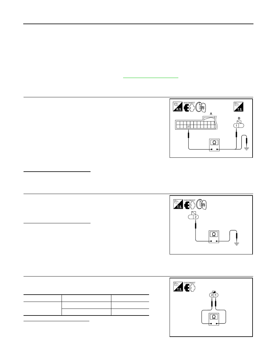
CHECK WASHER FLUID LEVEL SWITCH SIGNAL CIRCUIT

1. Turn ignition switch OFF.

2. Disconnect combination meter connector and washer fluid level

switch connector.

3. Check continuity between combination meter harness connector

M24 (A) terminal 37 and washer fluid level switch harness con-

nector E106 (B) terminal 1.

4. Check continuity between combination meter harness connector

M24 (A) terminal 37 and ground.

Is the inspection result normal? 

YES

>> GO TO 2

NO

>> Repair harness or connector.

2.

CHECK WASHER FLUID LEVEL SWITCH GROUND CIRCUIT

Check continuity between washer fluid level switch harness connec-

tor E106 terminal 2 and ground.

Is the inspection result normal? 

YES

>> Inspection End.

NO

>> Repair harness or connector.

Component Inspection

INFOID:0000000006164932

1.

CHECK WASHER FLUID LEVEL SWITCH

Check continuity between washer fluid level switch terminals 1 and

2.

Is the inspection result normal?

YES

>> Inspection End.

NO

>> Replace washer fluid level switch.

37 - 1

: Continuity should exist.

37 - Ground

: Continuity should not exist.

AWNIA0111ZZ

2 - Ground

: Continuity should exist.

AWNIA0112ZZ

Terminal

Washer fluid level

Continuity

1 - 2

Low

Yes

Other

No

AWNIA0113ZZ

MWI

COMBINATION METER

MWI-43

< ECU DIAGNOSIS INFORMATION >

C

D

E

F

G

H

I

J

K

L

M

B

A

O

P

ECU DIAGNOSIS INFORMATION

COMBINATION METER

Reference Value

INFOID:0000000006164934

TERMINAL LAYOUT

PHYSICAL VALUES

WKIA5724E

Termi-

nal

Wire 

color

Item

Condition

Reference value (V)

(Approx.)

Ignition 

switch

Operation or condition

1

O

Ignition switch ACC or 
ON

Battery voltage

2

P

Air bag warning lamp in-
put

ON

Air bag warning lamp ON

4

Air bag warning lamp OFF

0

8

P

Battery power supply

Battery voltage

9

B

Ground

0

11

L

CAN-H

12

P

CAN-L

14

L

DIFF LOCK indicator in-
put

ON

DIFF LOCK indicator ON

0

DIFF LOCK indicator OFF

Battery voltage

15

Y/L

Fuel level sensor signal

Refer to 

MWI-12, "FUEL GAUGE : System 

Description"

.

16

B/P

Fuel level sensor ground

ON

0

17

R/G

Stop lamp switch

Brake pedal depressed

Battery voltage

Brake pedal released

0

18

P/B

Brake fluid level switch

ON

Brake fluid level low

0

Brake fluid level normal

Battery voltage

23

G

Parking brake switch

ON

Parking brake applied

0

Parking brake released

Battery voltage

24

O/L

Ignition switch ON or 
START

ON

Battery voltage

27

O/B

Seat belt buckle switch 
LH

ON

Unfastened (ON)

0

Fastened (OFF)

Battery voltage

28

G/O

Security indicator input

OFF

Security indicator ON

0

Security indicator OFF

Battery voltage

MWI-44

< ECU DIAGNOSIS INFORMATION >

COMBINATION METER

Fail Safe

INFOID:0000000006164936

The combination meter performs a fail-safe operation for the functions listed below when communication is

lost.

29

W/R

Vehicle speed signal out-
put (8-pulse)

ON

Speedometer operated
[When vehicle speed is ap-
prox. 40 km/h (25 MPH)]

NOTE:
Maximum voltage may be 12V due to spec-
ifications (connected units).

37

W/L

Washer fluid level switch

ON

Washer fluid level low

0

Washer fluid level normal

Battery voltage

41

P/L

Seat belt buckle switch 
RH

ON

Unfastened (ON)

0

Fastened (OFF)

Battery voltage

45

BR/W

Generator

ON

Generator voltage low

0

Generator voltage normal

Battery voltage

50

BR

Illumination output

Refer to 

INL-10, "System Description"

.

52

B

Ground

0

Termi-

nal

Wire 

color

Item

Condition

Reference value (V)

(Approx.)

Ignition 

switch

Operation or condition

PKIC0643E

Function

Specifications

Speedometer

Zero indication.

Tachometer

Fuel gauge

Engine coolant temperature gauge

Engine oil pressure gauge (if equipped)

Voltage gauge (if equipped)

A/T oil temperature gauge (if equipped)

Illumination control

Meter illumination

Change to nighttime mode when communication is lost.

Segment LCD

Odometer

Freeze current indication.

A/T position

Display turns off.

Buzzer

Buzzer turns off.

MWI

COMBINATION METER

MWI-45

< ECU DIAGNOSIS INFORMATION >

C

D

E

F

G

H

I

J

K

L

M

B

A

O

P

DTC Index

INFOID:0000000006164937

NOTE:

“TIME” indicates the following.

• 0: Indicates that a malfunction is detected at present.

• 1-63: Indicates that a malfunction was detected in the past. (Displays number of ignition switch OFF 

→ ON

cycles after malfunction is detected. Self-diagnosis result is erased when “63” is exceeded.)

Warning lamp/indicator lamp

ABS warning lamp

Lamp turns on when communication is lost.

Brake warning lamp

VDC OFF indicator lamp

SLIP indicator lamp

A/T CHECK warning lamp

Lamp turns off when communication is lost.

Oil pressure/coolant temperature 
warning lamp

Malfunction indicator lamp

Master warning lamp

Air bag warning lamp

High beam indicator

Turn signal indicator lamp

Driver and passenger seat belt warn-
ing lamp

Lamp turns off when disconnected.

Charge warning lamp

Security indicator lamp

4WD indicator lamp

ATP indicator lamp

DIFF LOCK indicator lamp

Low tire pressure warning lamp

Lamp will flash every second for 1 minute and then stay on con-
tinuously thereafter.

Function

Specifications

CONSULT-III display

Malfunction

Reference 

page

CAN COMM CIRC 
[U1000]

Malfunction is detected in CAN communication.

CAUTION:

Even when there is no malfunction on CAN communication system, malfunction may be 
misinterpreted when battery has low voltage (when maintaining 7 - 8 V for about 2 sec-
onds) or 10A fuse [No. 3, located in the fuse block (J/B)] is disconnected.

MWI-31

VEHICLE SPEED 
CIRC
[B2205]

Malfunction is detected when an erroneous speed signal is input.

CAUTION:

Even when there is no malfunction on speed signal system, malfunction may be misin-
terpreted when battery has low voltage (when maintaining 7 - 8 V for about 2 seconds). 

MWI-32


Content   ..  730  731  732  733   ..