Nissan Titan A60. Manual - part 731


  Index      Nissan     Nissan Titan A60 (2011 year) - Service and Repair Manual


Search            


Content   ..  729  730  731  732   ..


Nissan Titan A60. Manual - part 731


MWI-38

< DTC/CIRCUIT DIAGNOSIS >

FUEL LEVEL SENSOR SIGNAL CIRCUIT

3. Check continuity between fuel level sensor unit and fuel pump harness connector (A) and ground.

Is the inspection result normal?

YES

>> GO TO 3

NO

>> Repair harness or connector.

3.

CHECK FUEL LEVEL SENSOR UNIT GROUND CIRCUIT

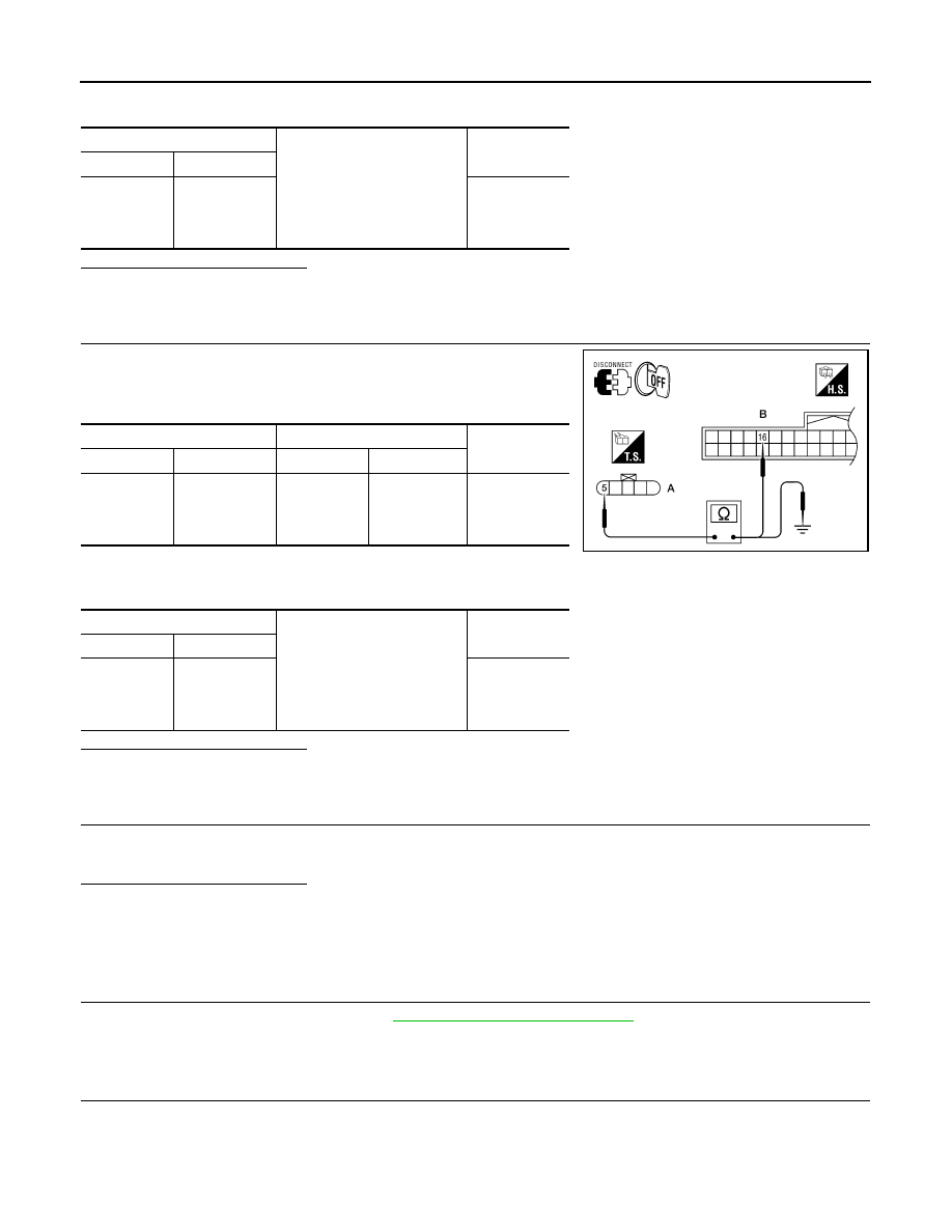
1. Check continuity between combination meter harness connector

(B) and fuel level sensor unit and fuel pump harness connector

(A).

2. Check continuity between fuel level sensor unit and fuel pump

harness connector (A) and ground.

Is the inspection result normal?

YES

>> GO TO 4

NO

>> Repair harness or connector.

4.

CHECK INSTALLATION CONDITION

Check fuel level sensor unit installation, and check whether the float arm interferes or binds with any of the

internal components in the fuel tank.
Is the inspection result normal?

YES

>> Inspection End.

NO

>> Install the fuel level sensor unit properly.

Component Inspection

INFOID:0000000006164921

1.

REMOVE FUEL LEVEL SENSOR UNIT

Remove the fuel level sensor unit. Refer to 

FL-11, "Removal and Installation"

>> GO TO 2

2.

CHECK FUEL LEVEL SENSOR UNIT AND FUEL PUMP

A

Ground

Continuity

Connector

Terminal

C7 (with 

Flexible Fuel)

C5 (without 

Flexible Fuel)

2

No

A

B

Continuity

Connector

Terminal

Connector

Terminal

C7 (with 

Flexible Fuel)

C5 (without 

Flexible Fuel)

5

M24

16

Yes

A

Ground

Continuity

Connector

Terminal

C7 (with 

Flexible Fuel)

C5 (without 

Flexible Fuel)

5

No

WKIA4618E

MWI

FUEL LEVEL SENSOR SIGNAL CIRCUIT

MWI-39

< DTC/CIRCUIT DIAGNOSIS >

C

D

E

F

G

H

I

J

K

L

M

B

A

O

P

Check the resistance between terminals 2 and 5.

*1 and *2: When float arm is in contact with stopper.

Is inspection result normal?

YES

>> Inspection End.

NO

>> Replace fuel level sensor unit and fuel pump. Refer to

FL-11, "Removal and Installation"

.

Terminal

Float position

mm (in)

Resistance value

(Approx.)

2

5

*1

Empty

7.5 (0.3)

80

*2

Full

218.9 (8.6)

6

LKIA0402E

MWI-40

< DTC/CIRCUIT DIAGNOSIS >

OIL PRESSURE SWITCH SIGNAL CIRCUIT

OIL PRESSURE SWITCH  SIGNAL CIRCUIT

Description

INFOID:0000000006164922

Detects the engine oil pressure and transmits the oil pressure switch signal to the IPDM E/R.

Component Function Check

INFOID:0000000006164923

1.

COMBINATION METER INPUT SIGNAL

1. Select “METER/M&A” on CONSULT-III.

2. Monitor “OIL W/L” of “DATA MONITOR” while operating ignition switch.

>> Inspection End.

Diagnosis Procedure

INFOID:0000000006164924

Regarding Wiring Diagram information, refer to 

MWI-65, "Wiring Diagram"

.

1.

CHECK OIL PRESSURE SWITCH CIRCUIT

1. Turn ignition switch OFF.

2. Disconnect IPDM E/R connector E122 and oil pressure switch

connector F4.

3. Check continuity between IPDM E/R harness connector E122

(A) terminal 42 and oil pressure switch harness connector F4 (B)

terminal 1.

Is the inspection result normal?

YES

>> Inspection End.

NO

>> Repair harness or connector.

Component Inspection

INFOID:0000000006164925

1.

CHECK OIL PRESSURE SWITCH

Check continuity between oil pressure switch and ground.

Is the inspection result normal?

YES

>> Inspection End.

NO

>> Replace the oil pressure switch.

OIL W/L
When ignition switch is in ON 
position (Engine stopped)

: ON

When engine is running

: OFF

Continuity should exist.

WKIA5607E

Condition

Oil pressure [kPa (kg/cm

2

, psi)]

Continuity

Engine stopped

Less than 29 (0.3, 4)

Yes

Engine running

More than 29 (0.3, 4) 

No

ELF0044D

MWI

PARKING BRAKE SWITCH SIGNAL CIRCUIT

MWI-41

< DTC/CIRCUIT DIAGNOSIS >

C

D

E

F

G

H

I

J

K

L

M

B

A

O

P

PARKING BRAKE SWITCH SIGNAL CIRCUIT

Description

INFOID:0000000006164926

Transmits the parking brake switch signal to the combination meter.

Component Function Check

INFOID:0000000006164927

1.

COMBINATION METER INPUT SIGNAL

1. Start engine.

2. Monitor “BRAKE” warning lamp while applying and releasing the parking brake.

>> Inspection End.

Diagnosis Procedure

INFOID:0000000006164928

Regarding Wiring Diagram information, refer to 

MWI-65, "Wiring Diagram"

.

1.

CHECK PARKING BRAKE SWITCH CIRCUIT

1. Disconnect combination meter connector and parking brake

switch connector. 

2. Check continuity between combination meter harness connector

M24 (A) terminal 23 and parking brake switch harness connec-

tor M11 (B) terminal 1.

3. Check continuity between combination meter harness connector

M24 (A) terminal 23 and ground.

Is the inspection result normal?

YES

>> Inspection End.

NO

>> Repair harness or connector.

Component Inspection

INFOID:0000000006164929

1.

CHECK PARKING BRAKE SWITCH

Check continuity between parking brake switch terminal 1 and switch

case ground.

Is the inspection result normal?

YES

>> Inspection End.

NO

>> Replace parking brake switch.

BRAKE warning lamp
Parking brake applied

: ON

Parking brake released

: OFF

23 - 1

: Continuity should exist.

23 - Ground

: Continuity should not exist.

AWNIA0109ZZ

Component

Terminal

Condition

Continuity

Parking brake switch

1

Parking brake applied

Yes

Parking brake released

No

AWNIA0018ZZ


Content   ..  729  730  731  732   ..