Nissan Titan A60. Manual - part 704
LU-14
< REMOVAL AND INSTALLATION >
OIL PUMP
OIL PUMP
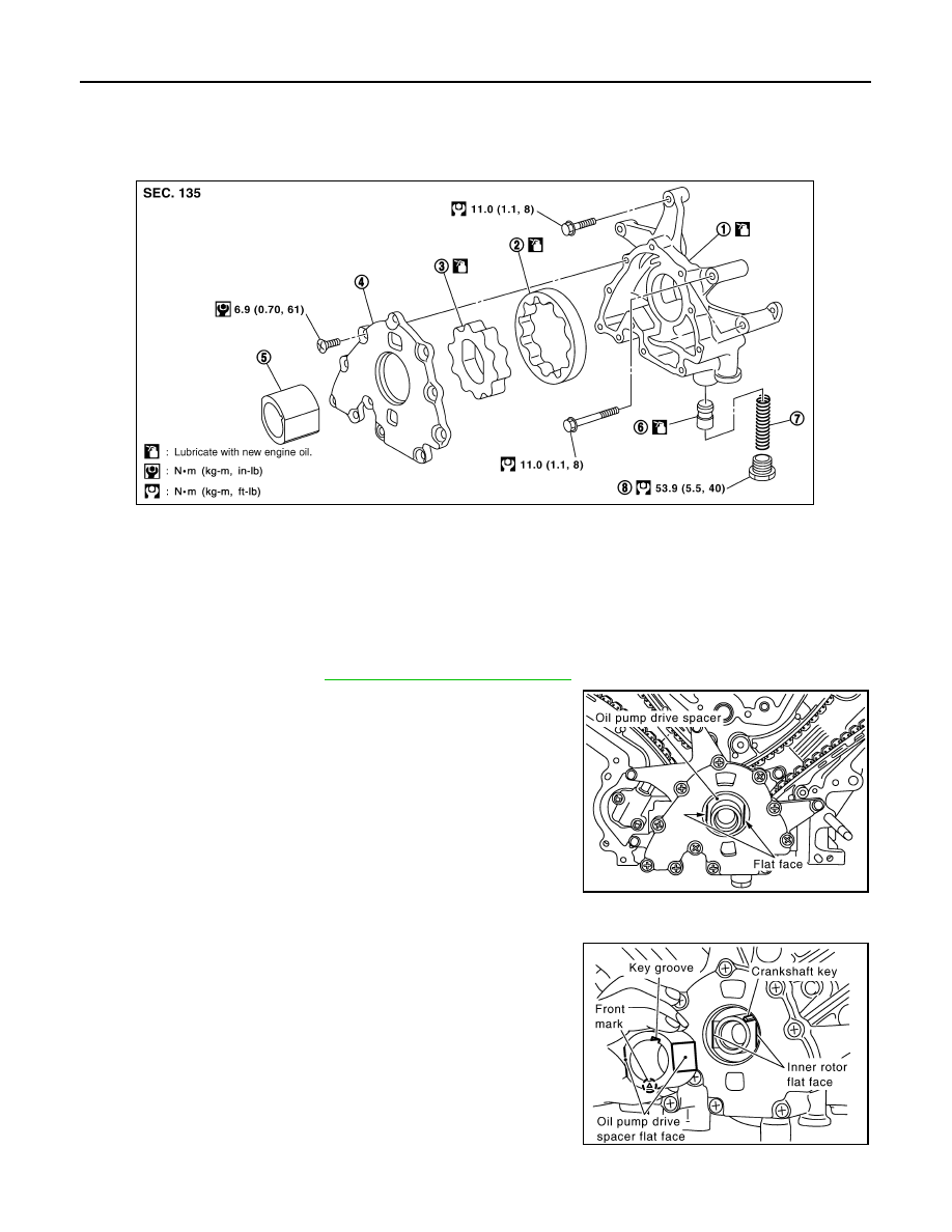
Exploded View
INFOID:0000000006158409
Removal and Installation
INFOID:0000000006158410
REMOVAL
1. Remove front cover. Refer to
EM-48, "Removal and Installation"
2. Remove the oil pump drive spacer.
3. Remove the oil pump.
INSTALLATION
Installation is in the reverse order of removal.
• When inserting the oil pump drive spacer, align the crankshaft key
and the flat face of the inner rotor.
• If they are not aligned, rotate the oil pump inner rotor by hand.
• Make sure that each part is aligned and tap lightly until it reaches
the end.
INSPECTION AFTER INSTALLATION
1.
Oil pump body
2.
Outer rotor
3.
Inner rotor
4.
Oil pump cover
5.
Oil pump drive spacer
6.
Regulator valve
7.
Regulator spring
8.
Regulator plug
WBIA0415E
KBIA2512E
KBIA2490E