Nissan Titan A60. Manual - part 648


  Index      Nissan     Nissan Titan A60 (2011 year) - Service and Repair Manual


Search            


Content   ..  646  647  648  649   ..


Nissan Titan A60. Manual - part 648


DIAGNOSIS SYSTEM (BCM)

INL-13

< SYSTEM DESCRIPTION >

C

D

E

F

G

H

I

J

K

M

A

B

INL

N

O

P

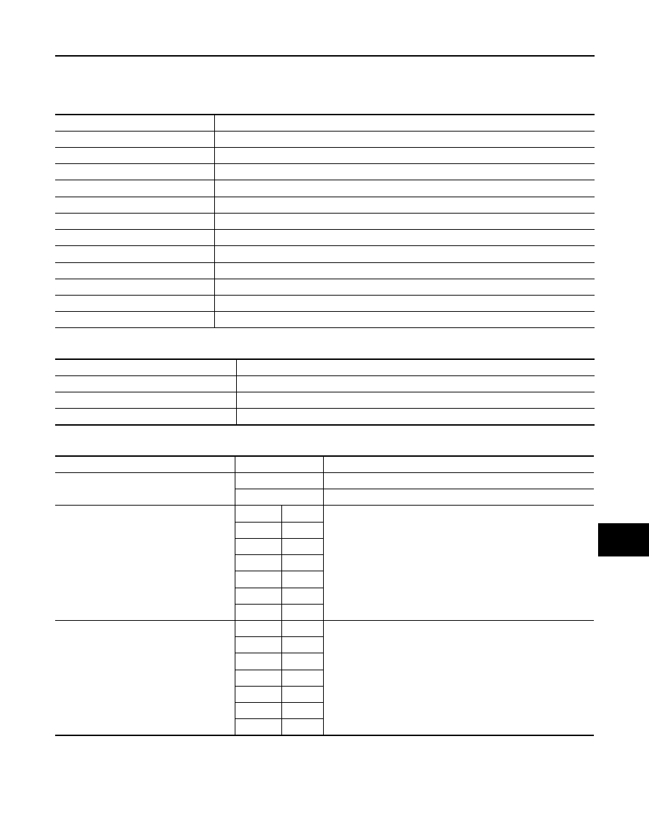
INT LAMP : CONSULT-III Function (BCM - INT LAMP)

INFOID:0000000006626886

DATA MONITOR

ACTIVE TEST

WORK SUPPORT

* : Initial setting

BATTERY SAVER

Monitor Item [Unit]

Description

IGN ON SW [On/Off]

Indicates condition of ignition switch ON position.

KEY ON SW [On/Off]

Indicates condition of key switch.

DOOR SW-DR [On/Off]

Indicates condition of front door switch LH.

DOOR SW-AS [On/Off]

Indicates condition of front door switch RH.

DOOR SW-RR [On/Off]

Indicates condition of rear door switch RH.

DOOR SW-RL [On/Off]

Indicates condition of rear door switch LH.

KEY CYL LK-SW [On/Off]

Indicates condition of lock signal from door key cylinder switch.

KEY CYL UN-SW [On/Off]

Indicates condition of unlock signal from door key cylinder switch.

CDL LOCK SW [On/Off]

Indicates condition of lock signal from door lock and unlock switch.

CDL UNLOCK SW [On/Off]

Indicates condition of unlock signal from door lock and unlock switch.

KEYLESS LOCK [On/Off]

Indicates condition of lock signal from keyfob.

KEYLESS UNLOCK [On/Off]

Indicates condition of unlock signal from keyfob.

Test Item

Description

INT LAMP

This test is able to check interior room lamp operation [Off/On].

STEP LAMP TEST

This test is able to check step lamp operation [Off/On].

LUGGAGE LAMP TEST

This test is able to check cargo lamp operation [Off/On].

Support Item

Setting

Description

SET I/L D-UNLCK INTCON

Off

Interior room lamp timer function OFF.

On*

Interior room lamp timer function ON.

ROOM LAMP ON TIME SET

MODE7

0 sec.

Sets the interior room lamp gradual brightening time.

MODE6

5 sec.

MODE5

4 sec.

MODE4

3 sec.

MODE3

2 sec.

MODE2*

1 sec.

MODE1

0.5 sec.

ROOM LAMP OFF TIME SET

MODE7

0 sec.

Sets the interior room lamp gradual dimming time.

MODE6

5 sec.

MODE5

4 sec.

MODE4

3 sec.

MODE3

2 sec.

MODE2*

1 sec.

MODE1

0.5 sec.

INL-14

< SYSTEM DESCRIPTION >

DIAGNOSIS SYSTEM (BCM)

BATTERY SAVER : CONSULT-III Function (BCM - BATTERY SAVER)

INFOID:0000000006626913

DATA MONITOR

ACTIVE TEST

WORK SUPPORT

*: Initial setting

Monitor Item [Unit]

Description

IGN ON SW [On/Off]

Indicates condition of ignition switch ON position.

KEY ON SW [On/Off]

Indicates condition of key switch.

DOOR SW-DR [On/Off]

Indicates condition of front door switch LH.

DOOR SW-AS [On/Off]

Indicates condition of front door switch RH.

DOOR SW-RR [On/Off]

Indicates condition of rear door switch RH.

DOOR SW-RL [On/Off]

Indicates condition of rear door switch LH.

KEY CYL LK SW [On/Off]

Indicates condition of lock signal from door key cylinder switch.

KEY CYL UN SW [On/Off]

Indicates condition of unlock signal from door key cylinder switch.

CDL LOCK SW [On/Off]

Indicates condition of lock signal from door lock and unlock switch.

CDL UNLOCK SW [On/Off]

Indicates condition of unlock signal from door lock and unlock switch.

KEYLESS LOCK [On/Off]

Indicates condition of lock signal from keyfob.

KEYLESS UNLOCK [On/Off]

Indicates condition of unlock signal from keyfob.

Test item

Description

BATTERY SAVER

This test is able to check battery saver operation [Off/On].

Support Item

Setting

Description

ROOM LAMP TIMER SET

MODE3

10 min

Sets the interior room lamp battery saver timer operating time. 

MODE2

60 min

MODE1*

15 min

POWER SUPPLY AND GROUND CIRCUIT

INL-15

< DTC/CIRCUIT DIAGNOSIS >

C

D

E

F

G

H

I

J

K

M

A

B

INL

N

O

P

DTC/CIRCUIT DIAGNOSIS

POWER SUPPLY AND GROUND CIRCUIT

Diagnosis Procedure

INFOID:0000000006626929

Regarding Wiring Diagram information, refer to 

BCS-46, "Wiring Diagram"

.

1.

 CHECK FUSES AND FUSIBLE LINK

Check that the following fuses and fusible link are not blown.

Is the fuse blown?

YES

>> Replace the blown fuse or fusible link after repairing the affected circuit.

NO

>> GO TO 2

2.

 CHECK POWER SUPPLY CIRCUIT

1. Turn ignition switch OFF.

2. Disconnect BCM.

3. Check voltage between BCM harness connector and ground.

Is the measurement value normal?

YES

>> GO TO 3

NO

>> Repair or replace harness.

3.

 CHECK GROUND CIRCUIT

Terminal No.

Signal name

Fuses and fusible link No.

57

Battery power supply

22 (15A)

70

F (50A)

11

Ignition ACC or ON

4 (10A)

38

Ignition ON or START

59 (10A)

Connector

Terminals 

Power

source

Condition

Voltage (V) (Ap-

prox.)

(+)

(-)

M18

11

Ground

ACC 

power 

supply

Ignition 

switch 

ACC or 

ON

Battery voltage

38

Ground

Ignition 

power 

supply

Ignition 

switch ON 

or START

Battery voltage

M20

57

Ground

Battery 

power 

supply

Ignition 

switch 

OFF

Battery voltage

70

Ground

Battery 

power 

supply

Ignition 

switch 

OFF

Battery voltage

LIIA2415E

INL-16

< DTC/CIRCUIT DIAGNOSIS >

POWER SUPPLY AND GROUND CIRCUIT

Check continuity between BCM harness connector and ground.

Does continuity exist?

YES

>> Inspection End.

NO

>> Repair or replace harness.

BCM

Ground

Continuity

Connector

Terminal

M20

67

Yes

LIIA0915E


Content   ..  646  647  648  649   ..