Nissan Titan A60. Manual - part 588
INTAKE DOOR MOTOR
HAC-35
< DTC/CIRCUIT DIAGNOSIS >
[AUTOMATIC AIR CONDITIONER]
C
D
E
F
G
H
J
K
L
M
A
B
HAC
N
O
P
INTAKE DOOR MOTOR
System Description
INFOID:0000000006164693
SYSTEM DESCRIPTION
SYMPTOM:
• Intake door motor does not operate normally.
• Intake door does not change.
SYSTEM DESCRIPTION
Component Parts
Intake door control system components are:
• Front air control
• Intake door motor (PRB built into the intake door motor)
• In-vehicle sensor
• Ambient sensor
• Optical sensor
• Intake sensor
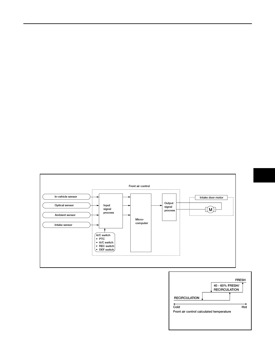
System Operation
The intake door control determines the intake door position based on the position of the recirculation switch.
When the recirculation switch is depressed the intake door motor rotates closing off the fresh air inlet and
recirculating the cabin air. If the recirculation switch is depressed again, the intake door motor rotates in the
opposite direction, again allowing fresh air into the cabin.
In the AUTO mode, the front air control determines the intake door position based on the ambient tempera-
ture, the intake air temperature and the in-vehicle temperature. When the DEF, D/F, FOOT or OFF switches
are pushed, the front air control sets the intake door at the fresh position.
Intake Door Control Specification
COMPONENT DESCRIPTION
WJIA1915E
WJIA0436E